
It involves encapsulating the optical chip in a metal box filled with inert gas (usually helium) to protect the optical elements from external environmental influences and enhance heat dissipation. COB, BOX, and TO-CAN packaging each offer unique advantages tailored to specific applications. COB packaging integrates components directly onto a PCB, enabling miniaturization and cost efficiency. BOX packaging seals optical chips in a metal enclosure with inert gas, ensuring long-term stability. The COB process refers to a technology that directly mounts bare chips onto a printed circuit board (PCB), connects them via gold wire bonding, and then encapsulates and protects the chips and wires using organic adhesive. Compared with conventional processes, the COB process offers high packaging. Box, COB, and TO can are currently the most prevalent packaging forms for optical components. Box packaging, also known as hermetic sealing, has a long history. Common optical device packaging methods include COB (chip-on-board packaging), BOX and coaxial packaging. What is COB technology? COB (Chip on board) is a form of packaging that directly bonds the. The invention provides an SFP28 SR optical module structure of a COB process, and belongs to the field of optical module structures. The micro-optical module comprises a shell, an unlocking mechanism, an EMI shielding structure, a circuit board, a micro-optical module arranged at one end of the.
[PDF]

These general purpose fiber clamps provide easy means for incorporating glass or plastic optical fibers into optomechanical post assemblies or SM1-threaded components. The precision V-groove and rubber pad are designed to clamp onto the buffer of single mode or multimode fibers without damaging. Harwin supplies a range of surface-mount shield can clips to provide a straight-forward, easy-to-use board-level shielding solution. The combination of SMT clips with a shield can provides a simple and cost-effective method of shielding vulnerable or EMI-radiating board components. Harwin's shield. Check each product page for other buying options. 2-piece kit Fiber optical thermal stripper M8 & fiber optical cleaning clip compatible with bare fiber/bundle and ribbon fiber for 1-48 core dual heating mode and 8-level temperature regulation. Need help?. FPH Fiber Chucks and Holders are designed to terminate bare optical fibers and provide precise coupling and mounting within optical systems. Compatible strain relief boots and fiber clamps are also available. Clamps are larger than clips and designed to hold multiple cables and wires together. Blind plugs are used to close. 1-800-363-1992 Have any questions? Talk with us directly using LiveChat.
[PDF]

BBU end can be connected to CWDM coarse wavelength division multiplexer through CWDM color optical module and OS2 single mode optical fiber patch cord, and then transmitted to CWDM coarse wavelength division multiplexer with one or two optical fibers. The operation of base stations requires a large number of optical modules for interconnection between devices, and we will talk about the application of optical modules in mobile communication base stations. Communication base station is composed of machine room, base station, antenna, feeder. The base station can be divided into two modules: the RRU for transmitting signals and the BBU for processing signals. The BBU is small and exquisite, with low power consumption, while the RRU is large and has high power consumption. In 4G networks, the optical modules used to connect BBU and RRU are mainly gigabit to 10Gbit optical modules. In modern server racks, the wrong optical choice can silently tax performance: queues grow, link training becomes flaky, and operators end up swapping modules mid-quarter. In 5G networks, CPRI is also upgraded to eCPRI. Currently, 5G of the bearer network mainly uses 25Gbps optical.
[PDF]

Continuous-wave operation (cw operation): The laser is continuously pumped and emits light continuously, either on a single resonator mode (→ single-frequency operation) or on multiple modes (see also: single-mode operation). How do optical. EML stands for Externally Modulated Laser (corrected from "External Modulated Laser"). Its basic principle is to supply a constant current to the laser diode, ensuring the LD emits continuous, stable light. An external electro-absorption modulator (EAM) then adjusts light transmittance to generate. A wavelength swept light source emits laser light with a continuously sweeping wavelength. It is suitable for shape measurement and displacement measurement utilizing OFDR (Optical Frequency Domain Reflectometry), an optical sensing method using the coherence of laser light. The transmitting interface inputs electrical signals of a certain bit rate, which are then processed by internal driver chips. Subsequently, the driver semiconductor laser. Industry pundits have recently speculated that demand for 100G/400G switches may take off in 2019, prompting optical transceiver module vendors to sample data center switches with high data transmission rates earlier than expected. As data center operators accelerate upgrades in preparation for 5G.
[PDF]
In fiber-optic communications, wavelength-division multiplexing (WDM) is a technology which multiplexes a number of optical carrier signals onto a single optical fiber by using different wavelengths (i., colors) of laser light. This technique enables bidirectional communications over a. 📦 For purchasing, use the RP Photonics Buyer's Guide for wavelength division multiplexing. It provides an expert-curated supplier directory, buyer-focused technical background information, and structured selection criteria to support professional procurement decisions. The chapter begins with a quick historical account of the origin of optical communication and its exponential growth following the invention of erbium oped fiber amplifier (EDFA) leading to the widespread adoption of WDM. Although inter-DCIs based on intensity modulation and direct detection (IM-DD) along with wavelength-division multiplexing technologies exhibit power-efficient and large-capacity properties, the requirement of multiple laser sources leads to high costs and limited scalability, and the chromatic. Wavelength division multiplexing (WDM) can help network operators stay ahead of growing demand for bandwidth. Read on to learn the fundamentals of this useful technology. The concept involves sending multiple independent data streams down a single strand of fiber, much like transforming a single-lane road into a.
[PDF]

Usually, the 10G/25G grey light optical modules with a short transmission distance are applied for connecting AAU/DU with WDM/OTN/SPN. The connections between WDM/OTN/SPN network devices can be achieved by 10G/25G/50G/100G dual-fiber or single-fiber bidirectional. Compared with Draft A (2013-07-30), this issue includes the following new topic: 2. This section describes engineering specifications of an AAU, including input power and equipment specifications. 7. In 2/3/4G networks, 10Gbps optical modules are generally enough for CPRI interfaces. In 5G networks, CPRI is also upgraded to eCPRI. Currently, 5G of the bearer network mainly uses 25Gbps optical modules. Next, ETU-LINK will introduce the types of optical modules used by 10G SFP+ and 25G SFP28. What is the difference between the 5G bearer network and the traditional optical transmission network? The main difference is that 5G fronthaul needs to support CPRI/eCPRI protocol. Most of the AAU of 5G base stations are deployed outdoors. In order to resist harsh environments such as high. The optical modules used to connect BBU and RRU devices are optical modules and optical fibers. Product Versions The following table lists the product versions related to this document. 25G SFP optical module adopts the wavelength of 850nm, with an operating.
[PDF]

Run the following command to view detailed optical module information on the device interface: display transceiver interface <interface-type> <interface-number> verbose The command output is divided into two parts:. Run the following command to view detailed optical module information on the device interface: display transceiver interface <interface-type> <interface-number> verbose The command output is divided into two parts:. When the optical module on an interface is faulty, you can run the display commands to view information about the optical module. Related Information Video Identify a Huawei-Certified Optical Module Run the display transceiver [ interface interface-type interface-number | slot slot-id ] [ verbose ]. During use, reading optical module information helps understand its real-time operating status, enabling faster troubleshooting of link abnormalities. The following uses the Moduletek SFP-10G-LR module connected to a Huawei S6700 switch as an example to introduce how to read information of the. See the interface module via the optical display command information, including general information of the optical module, manufacturing information, and alarm information. If it is not a Huawei-certified optical module, replace it with a Huawei-certified optical module. If the optical module is installed on a GE port, run the display interfaceGigabitEthernet x/x/x command to view port information when the optical module.
[PDF]

In simple terms, Receiver Sensitivity is the minimum received optical power required at the input of a receiver for the system to achieve a specified performance level, typically defined by a maximum Bit Error Rate (BER). Think of it like listening to a distant radio station. The standards body governing the application sets this specified BER. For example, SONET specifies that the BER must be 10 -10 or better. Optical modules form the backbone of modern data center networks, enabling ultra-high-speed data transmission between servers, switches, and storage devices. In optical link design, the receiver performance parameters are like vital signs of the link, directly determining the reliability and. Receiver sensitivity shows the weakest signal your device can find. Good sensitivity gives stronger connections, even with weak signals. Always look at the dBm value in product details. A lower dBm means better receiver sensitivity. This helps you pick the best device. It denotes a module's capability to function in challenging environments and aids network operators in determining the system's maximum reach or link margin.
[PDF]

There are a total of 379 Optical Products Manufacturers in Africa as of April 01, 2026. (Google Earth) file formats. 98% increase from 2023. 75%. Promoted | NEC XON and Smartoptics are introducing a new era of pluggable optical solutions for Africa. For years, African. This section provides a list of the top 10 Optical Module manufacturers, Website links, company profile, locations is provided for each company. Also provides a detailed product description of the Optical Module, including product introduction, history, purpose, principle, characteristics, types. As specialized fiber optic transceivers manufacturer, Star Computer Limited is located in Johannesbur, South Africa. The company was founded in 1999, at first we mainly made cable assemblies, later we expanded our business to various kinds of fiber optic transceivers, our transceiver products types. The rapid development of AIGC has promoted the demand for 800G optical modules, and the entire industrial chain involving optical components, optical modules, and optical communication equipment is expected to fully benefit. To help you choose the best partner, this article will analyze and. Avago Technologies (now part of Broadcom Inc. ) is a global leader in high-performance optical and networking components. Their family of Small Form Factor Pluggable (SFP) LC optical transceivers is designed to deliver reliable, scalable, and energy-efficient connectivity across enterprise, data.
[PDF]

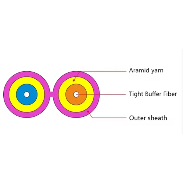
One of the core advantages of MPO patch cords is their high-density integration. Traditional patch cords have only 1-2 cores per cord, while MPO patch cords can integrate 12-48 cores, enabling multi-port connections with a single cord. Fiber cores are the heart of fiber optic cables, transmitting light signals that carry data. Made from either high-quality glass or plastic, the core plays a critical role in determining the cable's performance. The total number of cores for a 1pc fiber patch cable is calculated as the number of. Multi-core patch cords are fiber assemblies containing multiple fibers within a single cable jacket, typically available in 4, 6, 12, and 24-fiber configurations. The outer sheath is clearly marked with core count indicators. MTP/MPO cables are a class of high-density multi-core fiber optic connectivity solutions widely used in data centers and telecom networks, which are designed to achieve fast connection of multi-core fiber optics through a single interface. In the context of accelerating digitalization, the rational. The 16-core MPO patch cord, a high-density optical fiber connector, has become an ideal choice for 400G networks and beyond due to its superior optical performance, flexible compatibility, and efficient cabling capabilities. This report analyzes the key technical parameters, primary application.
[PDF]
HUAWEI WDM replacing the optical module video shows you how to replace an optical module. HUAWEI WDM Documentation:. Single-fiber bidirectional (BIDI) optical modules must be used in pairs. For example, SFP-10G-BXD1 must be used with SFP-10G-BXU1. If the SFP-10G-ER-1310 is connected. SFP Work on Cisco/Huawei/Arista/Juniper/MikroTik/Aruba/H3C/Fontinet/Ruijie etc Check my profile for tips. WhatsApp:86 13528869091 How to disassemble a 10G optical module? How to disassemble a 10G optical module?. Huawei's hn8145x6 idle fish costs more than 400 yuan, which is twice as expensive as the hs8145x6 and k662 previously disassembled. The reason for the price is that 10G Optical fiber module is more expensive, and the CPU is also different. Take down the machine and see what's going on. HUAWEI WDM Documentation:. The SFP (Small Form Factor Pluggable) or SFP+ transceiver is a critical component of fiber optic network cabling. It is used as a hot-swappable I/O device that plugs into a module slot for Gigabit transport. Failure to install an SFP or SFP+ transceiver can cause damage to the transceiver and the. This article will explore best practices for deploying 10G optical modules and offer tips for troubleshooting and maintaining their performance to maximize the longevity and efficiency of your network. Deploying a 10G transceiver requires meticulous planning and adherence to best practices to.
[PDF]

This guide provides a clear, step-by-step explanation of how to install an SFP module correctly, based on real-world deployment practices. The fastest way to do so is by unplugging the power plug from the power outlet. This is a Class A product. In a domestic environment, this product might cause radio interference in which case the user might be required to take adequate measures Electric shock hazard. This equipment is to be. This Quick Guide covers the model: CCR2004-16G-2S+PC. You can find the product model name on the case label (ID). Or scan the QR code with your mobile phone. lv/um The most important. The Installation of the equipment must comply with local and national electrical codes. Please read the mounting instructions carefully before beginning installation. Failure to use the correct hardware or to follow the correct procedures. The CCR2004 is a high-performance multicore router with twelve 10G SFP+ ports and two 25G SFP28 ports. Before you work on any equipment, be aware of the hazards involved with electrical circuitry, and be familiar with standard practices for preventing accidents. It covers critical preparation checks, proper insertion techniques, hot-swap and safety considerations, common installation mistakes, and practical. The Cisco 8000 series routers support both ZR and ZR+ modules. The Cisco 8200 Series uses a single Cisco Silicon One ASIC to deliver full routing functionality. These fixed port, high-density routers provide 10.
[PDF]
A passive optical network (PON) is a point-to-multipoint fiber network architecture that uses optical splitters to deliver high-bandwidth services from a single fiber to multiple end users without requiring active electronics in the field. While there are many subtle differences, a clear distinction between active optical networking and PON topology is PON's use of a. A passive optical network (PON) is a fiber-optic telecommunications network that uses only unpowered devices to carry signals, as opposed to electronic equipment. In practice, PONs are typically used for the last mile between Internet service providers (ISP) and their customers. In this use, a PON. A passive optical network sends data as light through fiber cables. You get internet, TV, and phone services with fewer cables and no powered splitters between you and your provider. What equipment do you need for PON at home? You need an optical network unit (ONU) at your home. By eliminating powered components between the service. Technology drives the broader adoption of passive optical LAN (also known as a passive optical local area network) across various sectors. Not having a long history as a passive optical network (PON), it is a better replacement for copper-based LANs in local area networks. This article covers every.
[PDF]

An Optical Time Domain Reflectometer (OTDR) is a precision tool used to detect faults and measure loss along fiber optic links by analyzing backscattered light from high-speed pulses. Download the PDF of the datasheet for an overview of the product features, important specifications, and ordering information. We are the measurement insight company committed to performance, and compelled by possibilities. Tektronix designs and manufactures test and measurement solutions to break. OTDR testing analyzes fiber optic cable performance from end to end by testing components along the cable, including connection points, bends, and splices. What Is an OTDR? What Is an OTDR? An OTDR is a powerful tool that helps technicians and engineers assess the health of fiber optic cables. Essential for both installation and maintenance, OTDRs ensure network reliability with accurate fault location. An OTDR (Optical Time Domain Reflectometer) is a measuring instrument intended to measure the transmission loss and distance of optical fibers, locate cable cuts, and evaluate the connection loss and reflectance (return loss) of fusion splices, mechanical splices, connector connections, etc. Also. Time Domain Reflectometry (TDR) is a well-established technique for verifying the impedance and quality of signal paths in components, interconnects, and transmission lines. The OTDR enables field technicians to rapidly, reliably, and.
[PDF]

This guide provides a complete framework for understanding, identifying, and planning MPO connector gender in data center environments. Visually, male and female MPO connectors are easy to distinguish: male connectors feature two alignment pins (PIN pins), while female connectors have corresponding holes instead of pins. An MPO connection is made between a male and female connector to make sure that there is proper alignment. Interfaces on active MPO equipment, such as transceivers are usually male, so any MPO trunk cable. In modern data centers and high-density fiber optic networks, MPO (Multi-Fiber Push-On) connectors have become an essential solution for achieving fast, reliable, and scalable connectivity. You will discover the physical distinctions between male and female connectors and how to develop a gender strategy for your infrastructure, which gender connects. Whether you're supporting parallel optics like 100G SR4 or densifying an optical distribution frame (ODF), MPO is now a cornerstone of network design. This article explains: And a practical checklist to design MPO systems that scale cleanly. If you only remember one thing: MPO is a multi-fiber. In MPO and MTP fiber connector systems, Male vs Female and Pin vs No-Pin describe the same core engineering attribute: the presence or absence of alignment pins on the MT ferrule. Unlike single-fiber connectors such as LC or SC, this distinction is not optional terminology but a mandatory.
[PDF]