
What is the main cause of attenuation in fiber? Attenuation in fiber mostly happens from absorption and scattering. The fiber material takes in some light as it moves. Both of these things make the signal weaker as it goes through the. Optical Signal Attenuation is the single greatest factor limiting the distance and performance of your network. Understanding it is crucial for anyone involved in data centers, telecommunications, or enterprise networking. This guide will demystify signal loss, explore its causes, and show you how. Optical fibers are a key component in modern communication systems, carrying signals over long distances. However, even the most advanced optical fiber suffers from attenuation, which is the loss of signal power as it travels along the fiber. Understanding the causes of signal loss and implementing mitigation strategies is essential for maintaining network efficiency. From infrastructure planners to telecom engineers. Optical fiber technology enables rapid data transmission over vast distances by guiding light signals through thin strands of glass. Losses can be introduced by various means such as intrinsic material absorption, scattering, bending, connector loss and more.
[PDF]

Fiber optic loss calculation formula: Total link loss (LL) = Cable attenuation + Connector attenuation + Fusion attenuation [Note: If there are other components (such as attenuators), their attenuation values can be added]. Intrinsic Optical Fiber Losses comprise of absorption loss, dispersion loss and scattering loss caused by the structural defects. The detailed information about these optical losses and how to reduce them are. Calculate fiber optic signal loss based on cable length, attenuation, and connector losses. Determine cable loss, connector loss, and total system loss in decibels (dB) to assess signal quality and repeater requirements. Fiber optic loss is calculated in two parts: cable loss and connector loss. This calculator determines fiber loss based on input power, output power, and the length of the fiber optic cable. In summary, fiber optic loss is. Use this worksheet to input values for all variables that will impact your system's performance. After entering your values, please ensure you click the 'Calculate Link Loss' button at the bottom of the page to generate your total link loss. This step is necessary to see if your system falls within. Optical fiber loss is a term for signal loss affecting transmission reliability. Optical fiber loss is.
[PDF]

An armored optical cable is a type of fiber optic cable reinforced with a protective layer—usually corrugated steel tape (STA) or steel wires (SWA) —to shield the internal fibers from external threats such as crushing, rodent bites, moisture, and harsh installation conditions. With a durable protective layer, they are ideal for harsh or high-traffic environments. This article explains what armored fiber cables are, their key. Every optical fiber cable project faces the same critical question: should you choose an armored cable or a non-armored one? At first glance, the choice may look simple. Armored cables appear stronger, non-armored cables are cheaper. But the real decision is not that easy. The wrong choice can: Or. With the increasing demands on high-performance connectivity, for many buyers, choices boil down to two quite popular options: the outdoor armored fiber optic cable and the standard optical fiber cable. In this blog post, we'll explore the advantages and disadvantages of. Armored and non-armored fiber optic cables are engineered for different levels of mechanical protection, environmental resistance, and installation conditions. You select between them based on route exposure, rodent risks, burial requirements, tension loads, and overall ODN architecture. An under-armored cable in a harsh environment leads to fiber damage, network outages, and costly repairs. Over-specifying armored cable where standard cable suffices.
[PDF]

The main components of a splice box are the splice cassette that picks up the fibers and their reserves, and the front panel which contains different connectors for transmitting signals via copper or fiber optic cables. A splice box (also known as splice distributor) is a housing in which fiber optic cables begin or end. Fiber optics are fanned out in splice boxes that are situated at the end of fiber optic transmission paths. It typically consists of two parts: an outer housing and an internal structure. In this response, we will focus on the. The FSB series of indoor wall mount enclosures are designed for centralized splice-only applications. These boxes are well suited as optical cable splice collection points for DAS (Distributed Antenna Systems), MTU (Multi-Tenant Unit) commercial business applications, and MDU (Multi-Dwelling Unit). Fiber optic splice closures permanently connect two fiber optic cables together and have a splice that protects the components. The optical cable connection part, that is, the optical cable joint, is the part that protects the connection between two or more optical cables by the optical cable. Splicing refers to the permanent connection of two optical fibers to form a continuous optical connection.
[PDF]
This updated list ranks the 20 largest fiber-optic cable companies worldwide and summarizes what each vendor is best known for—core product lines, regional strengths, and typical project fit. Use it as a fast shortlist when planning new FTTH/FTTA or data-center builds. Based on 2025 rankings from industry sources like Owire and TSCables, the top manufacturers are evaluated on market share, innovation, and global reach. We note certifications. Top 10 Fiber Optic Cable Manufacturers in 2025: Who to Choose & Why? Here's an updated list of the best fiber optic cable manufacturers, with FS and PHILISUN among the leaders driving innovation and connectivity worldwide. Selecting the right fiber optic company is the first critical step in. With the global fiber optic cable market valued at $13. 92 billion and growing at 10. 46% annually, choosing from the best fiber optic manufacturers ensures your business infrastructure meets current demands and future scalability requirements. 80% during the forecast period (2023-2032). This expansion is driven by surging demand for high-bandwidth networks, 5G.
[PDF]

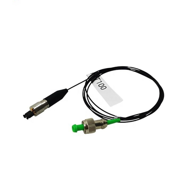
The max insertion loss of a fiber patch cable is 0. 75 dB (the maximum acceptable value) in the TIA standard. Insertion loss (IL) and return loss (RL) are key performance indicators of fiber optic patch cords. This article explains their concepts, standards, testing methods, and FiberMania's quality assurance workflow to ensure optimal network performance. Fiber optic patch cords are crucial components in. A: Fiber optic loss refers to the reduction in signal strength as it travels through the fiber optic cable. This can be due to various factors, including attenuation, connectors, and splices. Q: How is fiber optic loss measured? A: Fiber optic loss is typically measured using an Optical Loss Test. The estimate, called a "loss budget" is calculated using typical component losses for each part of the cable plant - the fiber, splices and/or connectors. If the measured loss exceed the calculated loss by a significant amount (remembering the inherent uncertainty in all measurements), the system. Insertion loss is usually shortened to IL, and the unit of measurement for insertion loss is dBm. ) in transmission systems. It is the power attenuation of the signal after. At TARLUZ, we specialize in manufacturing high-performance fiber optic patch cords that comply with global industry standards, ensuring optimal signal integrity and long-term stability.
[PDF]

Optical connectors are the physical interface that links an optical device to a fiber optic cable. Fiber optics are used in many applications, including medical imaging, automotive, military, industrial, and commercial (e., telecommunications). Each of these. Many people ask the same question: Can you use a fiber optic cable with an RJ45 port? The short answer is no - RJ45 connectors are designed for electrical Ethernet signals, while fiber optics transmit light pulses through glass or plastic. However, modern networks often combine both technologies. An optical fiber connector is a device used to link optical fibers, facilitating the efficient transmission of light signals. An optical fiber connector enables quicker connection and disconnection than splicing. They come in various types like SC, LC, ST, and MTP, each designed for specific. Proper connection of fiber optic cables is essential to harness these benefits fully, as even minor errors can lead to significant performance issues like signal loss. This article will guide you through the necessary tools, materials, and methods on how to connect fiber optic cables effectively. Most SFP fiber optic modules use LC connectors, while SC connectors are mainly found in legacy networks and MPO/MTP connectors are used for high-density cabling rather than directly on standard SFP modules. FC FO LC connectors for fiber optic.
[PDF]
This unit is a nine output Composite Splitter with built in distribution amplifier. It is used to distribute composite video signals to multiple destinations with compatible outputs. Composite Splitter provides multiple outputs that are identical to the Video input signal. Check each product page for other buying options. Shop products from small business brands sold in Amazon's store. Learn more Need help? Discover optical fiber splitters designed for home. Optical splitters and couplers split or combine light—distributing signals injected into a single fiber strand to multiple fibers, enabling point to multi-point communication in Fiber To The Home (FTTH) networks based on ITU. T PON standards such as GPON, XGS-PON and new 25 and 50G standards. Cables Plus USA can supply custom fiber optic splitters to meet your specific requirements. Available in PLC splitters, also called Planar Lightwave Circuit. As well as FBT splitters Fused Biconical Taper splitters, which are two or. Only 1 left! Get the best deals on Corning Cable Splitters and Adapters and find everything you'll need to improve your home office setup at eBay. Fast & Free shipping on many items!. FS PLC Fiber Optic Splitters, Bare/Blockless/ABS/LGX Splitter/Rack Mount Types, support 1xN light distribution, with low IL and PDL for high-reliability transmission. Deploying compact FS PLC Splitters to simplify your networks, perfectly fits your PON, EPON, FTTX, etc. ZIP code to view pricing.
[PDF]
The communication system of fiber optics is well understood by studying the parts and sections of it. The major elements of an optical fiber communication system are shown in the following figure. The ba.
[PDF]

5 dB depending on splitter type. Common planning value: 0. Optional: patch panels, attenuators, or extra components. Helps cover dirt, aging, and measurement tolerances. Adds Rx power and margin calculation. Use 2×N when two inputs feed the same distribution stage. Wavelength is recorded in outputs for documentation. Optional: patch. FTTH / PON Splitter Loss Calculator - Zion Communication is a professional manufacturer of cables and accessories for signal and low voltage transmission. Estimate whether an FTTH or PON optical link is feasible by calculating PLC splitter loss, fiber attenuation, connector loss, splice loss and. In fiber optic networks, particularly in FTTx (Fiber to the x) and PON (Passive Optical Networks) deployments, splitters play a central role in distributing the optical signal from a single source to multiple destinations. These are known as passive optical splitters, and they perform the function. The formula for the theoretical loss for each output port of a splitter with N output ports is: Theoretical Split Loss (in dB) = 10 * log10 (N) Where: N is the number of output ports the splitter has (e., 2 for a 1x2 splitter, 4 for a 1x4, 8 for a 1x8, 32 for a 1x32, etc. Passive split links usually lose the most dB at the splitter, so we keep the optical budget and the installed route separate. These are especially important for FTTH (Fiber to the Home), data centers, and Passive Optical Networks (PON), where.
[PDF]

Fusion splicing is the process of fusing or welding two fibers together usually by an electric arc. Fusion splicing is the most widely used method of splicing as it provides for the lowest loss and least reflectance, as well as providing the strongest and most reliable joint between. This guide reveals the secrets to fusion splicing with little fluff—just proven, straightforward techniques refined from years of work in the field. The goal is to fuse the two fibers together in such a way that light passing through the fibers is not scattered or reflected back by the splice, and so that the splice and the region surrounding it are almost as strong as the. A fusion splicer is a specialized tool used in fiber optic networks to join two fiber optic cables together permanently. This process creates a strong and reliable connection that can withstand. Splicing fiber optic cable is an extremely important phase for making dependable, high-speed communication infrastructures. Fusion splicing stands out as a superior technique for joining optical fibers, offering a seamless, low-loss connection that is crucial for reliable fiber optic networks. Let's explore the fundamentals of mechanical and fusion.
[PDF]

The box is typically composed of several parts, including the enclosure, the splitter module, and the connectors. An optical cable split fiber box is a device used in fiber optic communication networks to split the signal from one input into multiple outputs, allowing multiple devices to be connected to a single fiber optic cable. This provides users with a dependable and high-speed network service and little to no wait times. There is no need for an FDB if there is no. In modern FTTH (Fiber to the Home) and optical communication networks, three types of fiber distribution products are widely used: Splitter Distribution Box, ODF (Optical Distribution Frame), and Fiber Terminal Box. Although they all belong to the optical distribution and management system, their. A fiber optic splitter is a passive optical component that divides a single incoming optical signal into two or more outgoing signals, or combines multiple incoming signals into one. It can divide the input optical signal into multiple output optical signals to meet the fiber optic access needs of multiple terminal devices. This type of device plays an important role in passive. In this kind of fiber cabinet, the backbone fiber optic cable usually does not connect to optical splitters. However, in some metropolitan area, the backbone fiber cable will.
[PDF]

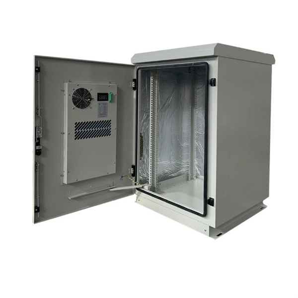
Here's a step-by-step guide to help you set up your fiber distribution box seamlessly: Before installing the fiber distribution box, ensure that your optical cables are properly prepared for connection. The optical fiber distribution box allows people to easily access the optical fibers in the box, and can well protect the optical fibers. In addition, the drawer structure also facilitates high-density wiring and good cable management. However, because optical fibers are fragile and can be easily. Keeping this page as a placeholder for now. Have any questions? Talk with us directly using LiveChat. Fix the rack to the ground with expansion bolts. Top installation: Dimensions of four connection holes on the top according to the. This instruction describes the installation of the Fiber Distribution Frame (FDF) manufactured by Corning Optical Communications. To order accessories that are purchased separately, contact Corning Optical Communications customer care for assistance. Read and understand this procedure (as well as. Optical fiber distribution frame is the wiring connection equipment between optical cable and optical communication equipment or between optical communication equipment. Distribution boxes are especially essential for FTTH networks, where they enable the efficient connection and management of optical fibers from a central.
[PDF]

Arduino-Powered Data Transmission with Fiber Optics Welcome to our video tutorial on optical communication with Arduino, designed to be easy t. more. They consist of a transmitter on one end of a fiber and a receiver on the other end. Most systems use a "transceiver" which includes both transmission and. I'm going to use HFBR 1414 fiber optic transmitter module which is manufactured by Broadcom. It is a low-cost high-power transmitter that is designed for use in industrial power generation, power distribution, medical transportation and gaming applications. Internally, the optical fiber consists of a highly reflective central core, which acts like a light guide. Media converters are special fiber optic transceivers used to convert from one type of cable (the media) to another, typically from copper cables to fiber optics, although some media converters will convert from one fiber type to another, e. multimode to singlemode. The FOA Guide has a page about. A fiber optic transceiver (also called an optical transceiver) is a compact module that both transmits and receives data signals through optical fibers. It serves a dual purpose — transmitting electrical signals as light pulses and receiving light pulses to convert them back into electrical form.
[PDF]

Mouser offers inventory, pricing, & datasheets for 8 Fiber Fiber Optic Cable Assemblies. Understanding the 8 core fiber optical cable price list is essential for businesses looking to invest in future-ready technology, as prices can vary significantly based on quality, application, and manufacturer. Whether you are a large corporation or a small enterprise, this guide will help you. Pricing (USD) Filter the results in the table by unit price based on your quantity. A tariff of 10% may be applied if shipping to the United States. A. Discover the perfect Optical Fiber addition with our 8 Core Optical Fiber Cable. Choosing OEM custom optical fiber manufacturing lets you specify details and order in bulk, which can drive cheap optical fiber cable pricing. This guide highlights cost-saving order strategies and reliable distributor. There are three primary types of 8-core fiber optic cables, each designed for specific performance needs, distance requirements, and application environments. The key differences between these types include core diameter, light source, transmission distance, bandwidth capacity, and typical use. An 8-core fibre optic cable is a high-density MPO (Multi-fibre Push-On) cable that integrates eight individual optical fibres within a single jacket. Featuring eight individual optical fibers protected by a durable metallic or non-metallic armor layer, these cables.
[PDF]
