
Manta HM (stands for "high magnification") is an automated microscope for inspection of single and multi-fiber patch cords, bulkhead and transceivers, including but not limited to: MT, MPO, SN-MT, MMC, LC, FC, SC, CS®, SN®, MDC, E2000™, MXC, PRIZM, QSFP, ARINC . Manta HM (stands for "high magnification") is an automated microscope for inspection of single and multi-fiber patch cords, bulkhead and transceivers, including but not limited to: MT, MPO, SN-MT, MMC, LC, FC, SC, CS®, SN®, MDC, E2000™, MXC, PRIZM, QSFP, ARINC . Image shown is a representation only. Exact specifications should be obtained from the product data sheet. Order today, ships today. F3-SDLCLC-HM – Cable Fiber Optic LC/UPC Duplex To LC/UPC Duplex 9/125 1. 64' (500mm) from CompuCablePlusUSA. Pricing and Availability on millions of electronic. Buy now, ships today. that performs on-site drawing of copper. When drawing copper, PCA starts with 13 AWG solid copper conductor on custom built deploying devices, called Stems. The copper is pulled into drawing. CESS, 3 HOLE OT P NG S, 3 HO.
[PDF]

Fusion splicing is the process of fusing or welding two fibers together usually by an electric arc. Fusion splicing is the most widely used method of splicing as it provides for the lowest loss and least reflectance, as well as providing the strongest and most reliable joint between. This guide reveals the secrets to fusion splicing with little fluff—just proven, straightforward techniques refined from years of work in the field. The goal is to fuse the two fibers together in such a way that light passing through the fibers is not scattered or reflected back by the splice, and so that the splice and the region surrounding it are almost as strong as the. A fusion splicer is a specialized tool used in fiber optic networks to join two fiber optic cables together permanently. This process creates a strong and reliable connection that can withstand. Splicing fiber optic cable is an extremely important phase for making dependable, high-speed communication infrastructures. Fusion splicing stands out as a superior technique for joining optical fibers, offering a seamless, low-loss connection that is crucial for reliable fiber optic networks. Let's explore the fundamentals of mechanical and fusion.
[PDF]

Fiber optic loss calculation formula: Total link loss (LL) = Cable attenuation + Connector attenuation + Fusion attenuation [Note: If there are other components (such as attenuators), their attenuation values can be added]. Intrinsic Optical Fiber Losses comprise of absorption loss, dispersion loss and scattering loss caused by the structural defects. The detailed information about these optical losses and how to reduce them are. Calculate fiber optic signal loss based on cable length, attenuation, and connector losses. Determine cable loss, connector loss, and total system loss in decibels (dB) to assess signal quality and repeater requirements. Fiber optic loss is calculated in two parts: cable loss and connector loss. This calculator determines fiber loss based on input power, output power, and the length of the fiber optic cable. In summary, fiber optic loss is. Use this worksheet to input values for all variables that will impact your system's performance. After entering your values, please ensure you click the 'Calculate Link Loss' button at the bottom of the page to generate your total link loss. This step is necessary to see if your system falls within. Optical fiber loss is a term for signal loss affecting transmission reliability. Optical fiber loss is.
[PDF]

To use a power meter for fiber optic testing, always clean connectors first with lint-free wipes or click-to-clean tools. Select the correct wavelength and set your reference. You measure optical power in dBm or insertion loss in dB. Consistent procedures ensure accuracy. Verify light travels from. The most basic fiber optic measurement is optical power from the end of a fiber. This measurement is the basis for loss measurements as well as the power from a source or presented at a receiver. Typically both transmitters and receivers have receptacles for fiber optic connectors, so measuring the. An optical power meter measures the strength of light traveling through a fiber optic cable, giving you a reading in dBm (decibels relative to one milliwatt). This article will guide you through the methods, instruments, and key considerations for measuring fiber. Fiber optic cabling is the high-performance core of today's datacom networks. As network speeds and bandwidth demands increase, fiber performance requirements have become more stringent. Fiber testing is more important than ever. An OPM uses a photodiode to generate an electrical current proportional to optical power.
[PDF]
Fiber testing is the process of verifying the performance of optical fiber cabling. This process includes a range of tests and measurements such as insertion loss, optical return loss, and fiber length. It encompass.
[PDF]

Fiber optic cables often follow a color-coding system to indicate their type: Single-mode fibers - Typically yellow. Multi-mode fibers (OM1 & OM2) - Usually orange or sometimes gray. Choosing the right type of fiber optic cable is essential for reliable and cost-effective network performance. The two main types — Single Mode (SM) and Multimode (MM) — differ in construction, performance, and application. This guide explains how to identify them by appearance, labeling, and. When figuring out if a fiber cable is single mode, one must know the different classifications. Essentially, fiber optics are mainly categorized as: Single Mode Fiber (SMF): This type features a small core and uses laser technology to send a single light mode. Single mode fibers are used for. Knowing how to tell the difference between single mode and multimode fiber is crucial for network efficiency; the core distinction lies in the fiber's core diameter and how light travels through it, affecting bandwidth, distance, and cost. This allows for a single mode of light to travel through the core. With clear tables and updated details, it serves as a comprehensive reference for technicians handling modern fiber optic installations. We'll cover single mode, multimode, and armored fiber cables below. This small diameter core, typically around 9 microns in diameter, allows only one.
[PDF]

Not all splitters are created equal. Here are the main types you'll encounter: The "1×N" notation indicates one input fiber and N output fibers. A 1×2 splitter divides the signal into two outputs, while a 1×8 splitter divides it into eight. The more splits, the. By dividing a single optical signal from a central Optical Line Terminal (OLT) into multiple outputs for Optical Network Terminals (ONTs) at users' homes, splitters eliminate the need for dedicated fibers to each residence—slashing infrastructure costs while scaling network reach. This guide. A fiber-optic splitter, also known as a beam splitter, is based on a quartz substrate of an integrated waveguide optical power distribution device, similar to a coaxial cable transmission system. The optical network system uses an optical signal coupled to the branch distribution. The fiber optic. Optical couplers can split or join signals in fibers. You can connect many users to one port with 1:n or 2:n splitters. These devices work both ways, which helps strong network communication. In a Passive Optical Network (PON), a single optical fiber carries massive amounts of data using light. They are named by the number of inputs and outputs, so a splitter with one input and 2 outputs is a 1X2, and a PON splitter with one input and 32 outputs is a 1X32.
[PDF]
3 specifies performance and transmission requirements for premises optical fiber cable, connectors, connecting hardware, and patch cords. Optical fiber transition methods used to connect cabling from an array connector to simplex or duplex connectors are also. ANSI/TIA-568-C. (FOA) was founded in 1995 to help develop the workforce to build the fiber optic networks to support a rapid expansion in communications and the Internet. The charter of the FOA was to promote professionalism in fiber optics through education, certification, and. ANSI/TIA‑568. 3‑E “Optical Fiber Cabling and Components Standard” was developed by the TIA TR‑42. 11 Optical Fiber Systems Subcommittee and published in September, 2022. A full catalog of TIA specs is at org/ Learning More About Standards and Codes There are a number of ways of finding out more about cabling. This specification covers the general requirements and characteristics for cables utilizing optical fibers for signal transmission. NOTE: The base document is not DLA Land and Maritime managed and is only here as a courtesy. Please use ASSIST Quick Search to ensure you have the latest version. This. This section covers Agency requirements for fiber optic service entrance cables intended for aerial installation either by attachment to a support strand or by an integrated self-supporting arrangement, for underground application by placement in a duct, or for buried installations by trenching.
[PDF]
Metal conductors in cables serve to conduct electricity, while optical cables use optical fibers to transmit light signals, and optical fibers are thin, flexible media that transmit light beams, forming the core part of optical cables. Let's take a closer look at. Yes, there can be differences between optical cables in terms of their construction materials, connector types, and the quality of the glass fibers used. These factors can affect the cable's ability to transmit data effectively over long distances and at high speeds. It's important to choose the. Toslink—short for “Toshiba Link”—is a very specific subset of fiber‑optic technology created in 1983 to move consumer‑level digital audio from one box to another. Let's take a closer look at these differences. Cables physically connect these devices, enabling them to communicate within a network. In computer networking, it is very important to know the distinctions between the different. These cables are used mainly for digital audio connections between devices. A fiber-optic cable, also known as an optical-fiber cable, is an assembly similar to an electrical cable but containing one or more optical fibers that are used to carry light. They are mainly used in telecommunications, data transmission and consumer electronics. Compared to traditional cables that carry electrical signals, optical ones have Cables some advantages.
[PDF]

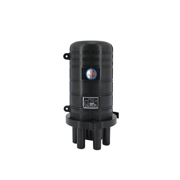
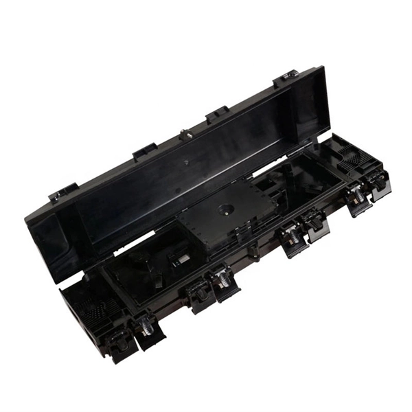
The box is typically composed of several parts, including the enclosure, the splitter module, and the connectors. An optical cable split fiber box is a device used in fiber optic communication networks to split the signal from one input into multiple outputs, allowing multiple devices to be connected to a single fiber optic cable. This provides users with a dependable and high-speed network service and little to no wait times. There is no need for an FDB if there is no. In modern FTTH (Fiber to the Home) and optical communication networks, three types of fiber distribution products are widely used: Splitter Distribution Box, ODF (Optical Distribution Frame), and Fiber Terminal Box. Although they all belong to the optical distribution and management system, their. A fiber optic splitter is a passive optical component that divides a single incoming optical signal into two or more outgoing signals, or combines multiple incoming signals into one. It can divide the input optical signal into multiple output optical signals to meet the fiber optic access needs of multiple terminal devices. This type of device plays an important role in passive. In this kind of fiber cabinet, the backbone fiber optic cable usually does not connect to optical splitters. However, in some metropolitan area, the backbone fiber cable will.
[PDF]

While nonarmored fiber optic cables don't require grounding due to their nonconductive properties, grounding is crucial when using armored fiber optic cables. Therefore, it is important to build a lightning protection system for fiber optic cables. How to Protect Fiber Optic Cable From Lightning? The major purpose of lightning protection systems is to conduct the high current lightning discharges safely into the Earth/ground. There are two main lightning. Fiber optic cable transmits data as light through glass or plastic strands, which means the fiber core itself carries no electrical current and requires no grounding. However, this does not mean every fiber optic installation is exempt from grounding requirements. Lightning-induced surges can travel through power lines, telecommunication lines, or nearby metallic structures and pose a. There are two main lightning protection grounding solutions in fiber networks, namely intermediate grounding and terminal grounding. These solutions use two ways of grounding for optical cable links both in domestic and foreign standards. However, because fiber optic cable has strengthened core, especially the direct-buried fiber optic cable has armoring layer.
[PDF]

Cable laying services install fiber optic cable or copper cable in buildings and office complexes, or over large distances. They are staffed by cable technicians who perform cable preparation, jointing, termination, testing, commissioning, maintenance, and troubleshooting tasks. Installing fiber optic cables underground involves far more than digging trenches and placing cables. It forms a critical backbone for modern communication networks across both urban and rural environments. Project success depends on careful planning, precise installation practices, and proper. Installing underground fiber optic cables is critical to establishing high speed internet infrastructure that delivers reliable connectivity for businesses nationwide. Unlike traditional copper systems, fiber optic cables require specialized handling techniques and precise installation methods to. These skilled professionals ensure that your home or business is equipped with the latest fiber optic technology, providing blazing-fast Internet speeds and robust connections. This guide walks you through the entire process of fiber cable installation, from the initial assessment to the final. This involves burying or installing fiber-optic cables along predetermined routes. During this phase, locators identify existing utilities to prevent damage.
[PDF]
Corning's ClearCurve bend-improved single-mode fibers provide lower cost, superior installation speed and efficiency, and greater successful installations. 15dB ultra low IL fiber optic cable is less attenuation when bent or twisted compared with traditional bend insensitive fiber cables and this will make the installation and maintenance of the fiber optic cables more efficient. Their market growth is directly tied to the expansion of high-speed internet access and innovative data transmission methods. The global fiber optic cable market is. Gain in-depth insights into Bend Insensitive Fiber Optic Cable Market, projected to surge from $ 1. 5 Bn by 2033, expanding at a CAGR of 7. Explore detailed market trends, growth drivers, and opportunities. 5 USD Million in 2024. The Bend Insensitive Fiber Optic Cable Market CAGR (growth rate) is expected. GL FIBER focuses on optical fiber OEM production services, and is committed to providing customers with brand customization, personalized packaging design, optimal cable structure design, and the best packaging design for international container transportation. GL FIBER® provides the whole series.
[PDF]

Optical transmission windows are specific wavelength ranges where light travels through fiber with minimal attenuation (signal loss) and dispersion (distortion). These low-loss windows are essential for maintaining the performance and reach of fiber optic communication systems. Fiber optic cable is a type of cabling that contains one or more optical fibers for transmitting data at high speeds and/or over long distances using light. These fibers are most commonly made of glass and are very thin, typically less than a tenth of the width of a human hair. Fiber optic cable. This is your "QuickStart" guide to testing fiber optic cable plants, patchcords and communications equipment with a fiber optic light source and power meter. We'll give you the basic information you need and provide some printable references. Optical power, required for measuring source power, receiver power and, when used with a test source, loss or attenuation, is the most. Fiber optic loss testing is an essential part of maintaining reliable, high-performance fiber optic networks because it helps identify potential issues and ensures that the system meets the required performance specifications. In this blog, we'll explore what a power meter and light source are and. This part of IEC 61280 is applicable to the measurement of attenuation of installed optical fibre cabling plant using multimode optical fibre.
[PDF]

Typical total project ranges and per-meter ranges with assumptions: A straightforward indoor fiber install with standard single-mode cable might cost about $0. 50 per meter for cable alone, with total project costs commonly in the $0. 50 per meter range when including labor. Fiber-optic cable materials typically cost $1 to $6 per linear foot, depending on fiber count and cable type. Commercial building installations with 100-200 network drops generally range from $15,000 to $30,000. Single-mode fiber costs less per foot than multimode fiber, but it requires more. Single-mode fiber (OS2): This is the industry workhorse. In 2025, the base glass price has stabilized. You are looking at $0. The price swing usually depends on the fiber count (e., 12-core vs 96-core) and brand. Generic. Buyers typically pay for fiber optic cable by length, fiber type, and installation complexity. Main cost drivers include cable grade (indoor vs outdoor, armoured), distance, and labor for trenching, splicing, and termination. This guide presents ranges in USD and practical price estimates to help. The unit cost of fiber optic cables can vary from $0. Here's a general pricing reference: Cable TypePrice Range (USD/meter)Simplex / Duplex Indoor Cable$0. 30Single-mode Outdoor Cable$0. 50Multimode (OM1/OM2/OM3)$0. On average, the cost can range from $2.
[PDF]
