Passive optical networks were first proposed by in 1987. Two major standard groups, the (IEEE) and the of the (ITU-T), develop standards along with a number of other industry organizations. The (SCTE) also specified f.
[PDF]

This complete guide explores everything you need to know about ODFs — from their structure, types, and key components, to installation best practices and modern design trends. Clients facing the exact demands of specialized environments—whether it's ultra-low-latency AI clusters, space-constrained military installations, or high-density telecom exchange points need more than off-the-shelf cabling. At FS, we place the customer at the heart of our operations. We are. This white paper provides a comprehensive guide to designing future-proof fiber optic networks, emphasizing a core-to-edge architectural approach. Key focus areas include backbone topologies, optical loss budgeting, standards compliance, and strategies for optimizing high-density environments like. In modern data centers and enterprise networks, Optical Distribution Frames (ODF) serve as the backbone for organizing, terminating, and managing fiber optic connections. As data centers, enterprises, telecom operators, and smart-building infrastructures deploy increasingly dense fiber links, ODFs provide the structured. Fiber optic network design refers to the specialized processes leading to a successful installation and operation of a fiber optic network. It includes first determining the type of communication system (s) which will be carried over the network, the geographic layout (premises, campus, outside.
[PDF]
Find all you need for professionally buying wavelength division multiplexing devices: a comprehensive expert-curated directory of suppliers, scientific and technical background information, and an interactive AI-based tool with guidance for a structured decision process. Why Choose Corning for Wavelength Division Multiplexers (WDM)? Corning's R&D scientists are constantly searching for new ways to improve wavelength division multiplexing (WDM) technology. CSRAYZER's Polarization Maintaining Filter WDM PMFWDM Series Product, is based. • Dense Wavelength Division Multiplexing (DWDM) Transceiver market size has reached to $2. 77 billion in 2025 • Expected to grow to $4. 9% • Growth Driver: Rising Demand For High-Speed Data Transmission Driving The Growth Due To. The global DWDM market is projected to reach $15. This expansion is primarily fueled by escalating bandwidth demands from hyperscale data centers, 5G deployments, and cloud services. As 5G, cloud, and AI workloads soar, DWDM is no longer a telecom-only domain—it's a digital economy enabler. In 2025, this market.
[PDF]
This article outlines five specific steps for repair: 1) Identify the break; 2) Cut out the damaged section; 3) Strip the cable; 4) Trim the fiber ends; 5) Test the repair. DIY fiber optic cable repair kits are increasingly popular for those who prefer home repairs. Before diving into repairs, it's essential to grasp the basics of fiber optic cables. These cables consist of a core (glass or plastic) that carries light signals, surrounded by cladding to reflect light inward, a buffer for protection, and an outer jacket for durability. Single-mode fibers (SMF). With the right tools and techniques, you can efficiently repair damaged fiber cables and restore reliable performance. The first step requires that you find the damage. To do this, you can use an OTDR, Optical Time Domain, Reflectometer. This is a testing device that looks at optical signals in the cable which can identify irregularities in the structure. This involves a set of specialized equipment such as a fusion splicer, fiber cleaver, and fiber stripper, among others. When it comes to ensuring nice network experiences for users, the condition of a fiber. A cut or damaged fiber optic cable can disrupt your network, but it is repairable with the right tools and techniques.
[PDF]
Backbone cable connects telecommunications spaces through dedicated infrastructure pathways, serving as the primary network connection between entrance facilities, equipment rooms, and telecommunications rooms. Structured cabling is an infrastructure that arranges the wires and cables of a building in an organized and modular way. In contrast to traditional point-to-point layouts, a structured cable setup clearly defines wiring standards. A structured cabling system is composed of six subsections, each. As data center environments scale in density and complexity, system integrators must make critical decisions about fiber architecture. Choosing between MPO and LC (Lucent Connector) fiber impacts compatibility, scalability, and deployment efficiency. Understanding how each solution fits within a. This Section defines the general design requirements for a uniform Intra and Inter-Building Communications Optical Fiber Backbone Cabling Infrastructure that shall be followed for all OFCC Technology construction projects. All equipment shall be UL listed. All equipment and Installation Practices. Fiber aggregation is a common technique used in fiber optic networks to improve the infrastructure and increase network capacity. So, what exactly are fiber aggregation points? They are the centralized hubs where multiple fiber optic cables intersect. My extensive experience shows that backbone cabling consists of fiber optic cables or.
[PDF]

Offering advanced EPON (Ethernet Passive Optical Network) technology, this ONU provides efficient data transmission, making it perfect for broadband services. With 1 Gigabit Ethernet (1Ge) ports, it supports fast internet speeds and enables seamless online experiences. ONU or Optical Network Unit is a type of optical device. Nowadays it is widely used as a media converter in internet services. The device used to convert the optical signals of the network into digital signals is called ONU. An ONU has one or more Ethernet ports that are used to connect to devices. An Optical Network Unit (ONU) is an important device in fiber optic networks, especially for FTTH (Fiber to the Home) connections. It works by connecting to the Optical Line Terminal (OLT) to deliver high-speed internet, voice, and video services directly to users. The BDCOM GP1702-1G Single Port GPON ONU is a high-performance, compact, and cost-effective optical network unit designed to bring reliable gigabit broadband connectivity to homes, offices, and small businesses. Ideal for ISPs, small towns, villages, and enterprises, this 2-port OLT delivers stable and scalable fiber internet connectivity at an affordable price.
[PDF]
A fiber optic backbone network is the central framework of a network that connects multiple sub-networks, systems, and devices using high-capacity fiber optic cables. It serves as the primary pathway fo.
[PDF]

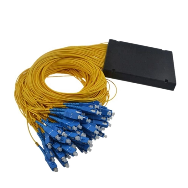
An Optical Splitter, also known as a beam splitter, is a passive optical device that divides a single input optical signal into two or more output signals. Conversely, it can also combine multiple signals into one. Knowing the difference between a splitter and an optical coupler helps you build better networks. You make your network work better when you pick the right device for each job. You can connect many users to one port with 1:n or 2:n splitters. By dividing a single optical signal from a central Optical Line Terminal (OLT) into multiple outputs for Optical Network Terminals (ONTs) at users' homes, splitters eliminate the need for dedicated fibers to each residence—slashing infrastructure costs while scaling network reach. This guide. In a Passive Optical Network (PON), a single optical fiber carries massive amounts of data using light. Signal Input: The fiber splitter receives the optical signal from the upstream network node and enters the splitter through the input fiber. Signal Distribution: Inside the splitter, according to the design structure and different. Splitters are passive optical devices that divide or combine optical signals, and they come in various types, including power splitters, uneven splitters, and wavelength-division multiplexing (WDM) splitters. Each type serves specific applications, enabling efficient use of optical infrastructure.
[PDF]

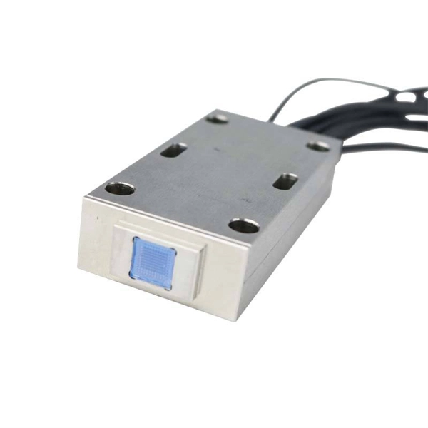
The optical module is usually composed of Transmitter Optical Subassembly (TOSA, containing a laser LD Chip), Receiver Optical Subassembly (ROSA, containing a photodetector PD Chip), a driving circuit, and an optical and electrical interface. Its schematic is shown in. This section explains the structure of a typical pigtail butterfly module, which gets its name from the two rows of seven leads at right angles on each side of the metal package plus an optical fiber pigtail at one end (Fig. Let's look at the internal structure (Fig. 2) of a common butterfly. Optical modules are devices used to connect network devices, transmit and receive data between network devices, and can be used to convert optical and electrical signals. The optical module is a very important component in an optical communication system. Optical devices are the core components of optical modules. TOSA and ROSA in Common Optical Transceiver Modules For ordinary optical transceiver modules, there are two optical devices, TOSA and ROSA, which have opposite effects.
[PDF]

Run the display transceiver [ interface interface-type interface-number | slot slot-id ] [ verbose ] command to view information about the optical module on a specified interface. In optical communication equipment, an optical module (Optical Module) contains several types of semiconductor chips that work together to complete the transmission and processing of optical signals. These chips typically include laser chips, photodetector chips, driver chips, transimpedance. When the optical module on an interface is faulty, you can run the display commands to view information about the optical module. Today, we will deeply analyze the four mainstream models of 100G QSFP28 dual-fiber optical modules: QSFP28-100G-SR4, QSFP28-100G-LR4, QSFP28-100G-ER4 and. The following uses the Moduletek SFP-10G-LR module connected to a Huawei S6700 switch as an example to introduce how to read information of the connected optical module on a Huawei switch. Figure 1 Schematic Diagram of Optical Module Connected to Switch 1. Optical Module Status Check Run the. Upgrade to 100G or 400G optics and save. Cisco Transceiver Modules - Learn product details such as features and benefits, as well as hardware and software specifications. Network administrators have a major challenge determining the right Cisco SFP modules, understanding complex model numbers that directly affect network performance and stability.
[PDF]

Explore 74 top manufacturers and suppliers of Optical Testing Instruments in our comprehensive photonics buyers' guide. An optical testing instrument is a device or system used to evaluate and measure the performance, quality, and characteristics of optical components. Source Photonics, founded in 1988 and based in Los Angeles, California, is a technology company that specializes in optical transceivers and data connectivity solutions. The company provides a wide range of products tailored for data centers, broadband, and optical transmission, serving. CACI designs and manufactures optical communications terminals for all of the major orbits in which our customer missions operate. These bespoke solutions are being manufactured in Orlando at CACI's space manufacturing and testing facility, which opened in June 2022. The facility is dedicated to. Manufacturer of standard and custom opticaltestequipment including microscopes, pocket comparators, disc gages, grids, scales, strips, slits, and micrometers. Suitable for optical, gaging, imaging, and calibration applications. Serves aviation industry. Lapmaster Wolters is estimated to have. Optical transceivers are devices that convert electrical signals into optical signals for transmission and reception. They are primarily used in communication systems that employ optical fiber cables, serving the purpose of signal conversion between the transmitting and receiving ends.
[PDF]

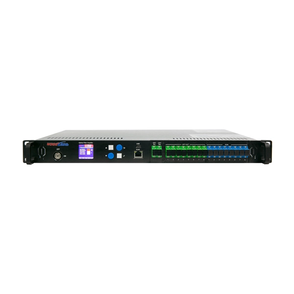
This report covers the optical, environmental, and mechanical performance of the LC-UPC, singlemode fiber optic BOAs, provided by Tyco Electronics, Fiber Optics Business Unit. Qualification testing was completed by a third party in July 2004. IDEAL FOR DEBUGGING OPTICAL POWER PERFORMANCE & OPTICAL INSTRUMENT CALIBRATION CORRECION & FIBER SIGNAL ATTENUATION. As optical passive devices, FS attenuators are mainly used in fiber optic to debug optical power performance & optical instrument calibration correction & fiber signal. L-com offers an extensive line of dual wavelength (1310/1550nm) Singlemode fiber optic attenuators. These versatile in-line attenuators are the perfect solution for attenuating Singlemode fiber connectors for both lab and commercial applications. Constructed of the highest quality materials and. zation system's perfo. the power of an optical signal. Our LC/APC single mode attenuators can handle a maximum o 1 watt of optical input power. This device contains one ale and one female LC/APC port. LC/APC optical attenuators can be ordered in attenuation. Fixed loopback type attenuators from OMC offer defined control of optical signals in both integrated and add-on products. Depending on the project or need, fixed attenuators can limit (attenuate) the amount of light passing through to the exact levels your project or application requirement.
[PDF]

Wavelength: 1310nm, 1550nm, or CWDM/DWDM wavelengths. LR (Long Range): 10km, 1310nm, Blue latch. Each SFP module operates at a specific wavelength, and to avoid confusion, manufacturers use color-coded pull rings for easy identification. Here's a quick guide: 🔹 850nm (Black) – Short-distance multimode fiber (up to 550m) 🔹 1310nm (Blue) – Longer reach, typically used for single-mode fiber (up. Wavelength division multiplexing modules differ from other optical modules in center wavelengths. Wavelength division. Coarse Wavelength Division Multiplexing (CWDM) SFP modules are a practical and cost-effective solution for expanding network capacity while keeping equipment simple and scalable. Selecting the right wavelength for CWDM SFPs is essential to ensure optimal performance, minimal interference, and. Every optical transceiver operates at a specific wavelength, typically measured in nanometers (nm). Their pull. SFP (Small Form-factor Pluggable) is a compact, hot-swappable module used in network devices such as switches, routers, and servers to provide network connectivity and is widely used in network communications. Think of it as the “translator” for your network equipment, converting electrical signals into optical signals.
[PDF]
On June 4, 2025, Chile's government and Google formalized an agreement to build the Humboldt Cable, a submarine fiber-optic line that will directly connect South America and the Asia-Pacific region. As of 2025, the plan is to build a 14,800-kilometre (9,200 mi) cable from Valparaiso, Chile, to. But what is complicated is the country being mired in a geopolitical crossfire between Japan and China Telecom in Chile has come a long way since its privatisation in 1980—having the most sophisticated and well-developed infrastructure in Latin America. In 2020, the Chilean government announced a plan to construct a subsea cable to connect Chile and Asia, followed two years later with an announcement to study the feasibility of a subsea cable between Chile and Antarctica. These projects offer opportunities to U. suppliers of fiberoptic and other. Chilean President Gabriel Borich delivered a speech on the construction of submarine fiber optic cable at the Asia-Pacific Economic Cooperation (APEC) CEO Summit on November 15, 2023, in San Francisco, California. Southeast Asia Japan Cable (SJC) 4. This project, first outlined in 2016 and developed through public-private partnership, will run.
[PDF]

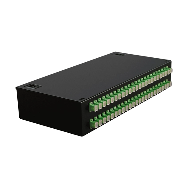
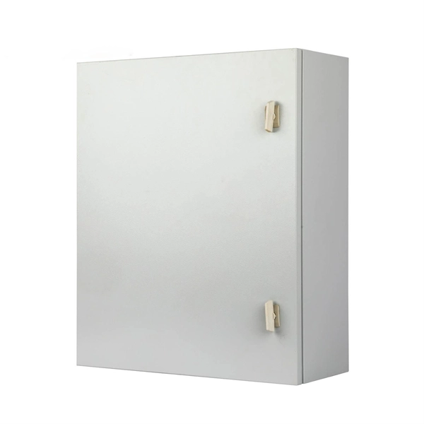
Here's a step-by-step guide to help you set up your fiber distribution box seamlessly: Before installing the fiber distribution box, ensure that your optical cables are properly prepared for connection. The optical fiber distribution box allows people to easily access the optical fibers in the box, and can well protect the optical fibers. In addition, the drawer structure also facilitates high-density wiring and good cable management. However, because optical fibers are fragile and can be easily. Keeping this page as a placeholder for now. Have any questions? Talk with us directly using LiveChat. Fix the rack to the ground with expansion bolts. Top installation: Dimensions of four connection holes on the top according to the. This instruction describes the installation of the Fiber Distribution Frame (FDF) manufactured by Corning Optical Communications. To order accessories that are purchased separately, contact Corning Optical Communications customer care for assistance. Read and understand this procedure (as well as. Optical fiber distribution frame is the wiring connection equipment between optical cable and optical communication equipment or between optical communication equipment. Distribution boxes are especially essential for FTTH networks, where they enable the efficient connection and management of optical fibers from a central.
[PDF]