Fusion Splicer Settings – Must-Know for Fiber Technicians! 🔧 At D-TECH TRADING, we're demonstrating the essential Fusion Splicer settings that every fi. more. Auto Mode is the most intuitive and user-friendly splice mode. The fusion splicer automatically detects the fiber type, such as single-mode (SM), multimode (MM), or dispersion-shifted (DS) fibers, and adjusts parameters like arc power and heating time accordingly. Applications: Ideal for beginners. Page 1 Fusion Splicer 19R+/70R+ Quick Reference Guide Splice Operation • When splicing only standard SM fibers (ITU-T G. 652), “SM AUTO” mode is recommended. It also outlines instructions for keypad usage. st Instruction manual Fusion Splicer Please read this instruction manual carefully before operating the equipment. Adhere to all safety instructions and warnings contained in this manual. Keep this manual in a safe place. There is a change without a previous notice. We are not responsible for the. Fusion splicing is the bedrock of high-performance fiber optic networks, enabling seamless signal transmission through permanent, low-loss fiber joins. As a leading provider of fiber optic infrastructure, Weunion leverages cutting-edge tools like the AI9 and AI10 fusion splicers, paired with.
[PDF]
The AWGs are used to multiplex channels of several wavelengths onto a single optical fiber at the transmission end and are also used as demultiplexers to retrieve individual channels of different wavelengths at the receiving end of an optical communication network. Arrayed waveguide gratings (AWG) are commonly used as optical (de)multiplexers in wavelength division multiplexed (WDM) systems. These design of these devices are based on an. A 32-channel 50-GHz spaced arrayed-waveguide grating with our innovative configuration has been designed and fabricated. The performance of the device has been fully tested by using a tunable laser light source, optical power meter, and polarization controller. AWG has filtering characteristics and versatility, which can obtain a large number of wavelengths and channels, to realize the multiplexing and demultiplexing. The arrayed waveguide grating (AWG) is a planar versatile light-dispersion component with high accuracy, robustness, and design flexibility. It has become an attractive component not only for telecommunication (e., multiplexer or demulti-plexer)[2,3] but also for medical imaging,[4–6]. uide Grating Routers (WGRs). The acronym AWG, introduced by Takahashi , is the most frequently used name today and wi l also be used in this text. Together with Thin-Film Filters and Fibre Bragg Gratings, AWGs are the most important filter type applied in WDM networks, and with the advance of.
[PDF]
The Planar Optical Waveguide Chip Market, valued at USD 1. 97B in 2026, is projected to reach USD 3. In this report, we will assess the current U. tariff framework alongside international policy adaptations, analyzing their. The global market for Planar Optical Waveguide Chip was valued at US$ million in the year 2024 and is projected to reach a revised size of US$ million by 2031, growing at a CAGR of %during the forecast period. Planar optical waveguide chip is a micro-optical device based on silicon-based. Planar Optical Waveguide Chip by Application (Optical Communication, Data Center, AI, Other), by Types (1xN, 2xN), by North America (United States, Canada, Mexico), by South America (Brazil, Argentina, Rest of South America), by Europe (United Kingdom, Germany, France, Italy, Spain, Russia. The Planar Optical Waveguide Chip Market was valued at USD 1. 97 billion in 2026, with a CAGR of 11. The evolution of planar optical waveguide chips demands a concise introduction that frames technology. This definitive report equips CEOs, marketing directors, and investors with a 360° view of the global Planar Optical Waveguide Chip market, seamlessly integrating production capacity and sales performance across the value chain. 2 USD Billion by 2035.
[PDF]

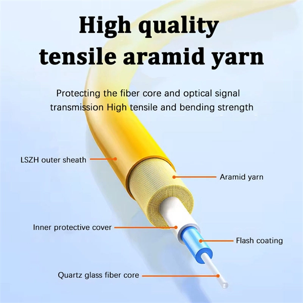
A Mode Conditioning Patch Cord (MCPC) is a specialized fiber patch cord designed to control the launch condition of light from a single-mode transmitter into a multimode fiber. Fiber optic cables primarily come in two types: Multimode Fiber (MMF): Has a larger core, allowing multiple light modes (paths) to travel. It's designed for short-distance, high-bandwidth applications within buildings or campuses. Common types are OM1, OM2, OM3, and OM4. Its primary purpose is to reduce differential mode delay (DMD) and prevent bandwidth limitation when legacy multimode. FS offers OM1 & OM2 mode conditioning fiber optic patch cables (MCP) in any connector & cable length, optimal for eliminating differential mode delay effects. This document describes the installation and use of the mode-conditioning patch cords listed in Table 1. 3z-compliant optical fiber assembly consisting of a single-mode fiber permanently coupled off-center to a 62. 5/125) fiber optic cable by offsetting the Singlemode Laser launch from the.
[PDF]

This is where a small but mighty hero comes into play: the Mode Conditioning Patch Cable (MCP). In this guide, we'll demystify what a mode conditioning patch cable is, why it's essential in specific network scenarios, and how it can save you from a world of connectivity headaches. This guide offers the key technical insights you need to select and install the optimal fiber optic cabling solutions for your specific needs. Covers the basics of fiber optic technology, including how light waves transmit data through thin strands of glass or plastic, and why fiber optics surpass. Fiber optic cables use light to transmit data, whereas traditional cables rely on electrical signals, which are more prone to interference and loss over distance. Connector types play a crucial. Fiber optic technology has transformed the way we transmit data, enabling faster, more reliable connections than traditional copper cables. Understanding fiber optic cable types is essential for anyone looking to build or maintain efficient fiber networks. We'll also. This is a plain-English guide for facilities and IT teams who want fiber that performs well, stays organized, and doesn't turn every add/change into a disruption. Start with the link's distance and speed, then pick single-mode (OS) or multimode (OM)—not the other way around.
[PDF]

In fiber-optic communication, a single-mode optical fiber, also known as fundamental- or mono-mode, is an optical fiber designed to carry only a single mode of light - the transverse mode. Modes are the possible solutions of the Helmholtz equation for waves, which is obtained by combining. Single-mode fiber is a specialized type of optical fiber designed to transmit light along a single, narrow path, or “mode. ” This technology is foundational to modern digital communication, enabling the high-speed transfer of massive amounts of data over vast distances. This type of fiber is used for transmitting signals over long distances. It is specified as the best for especially long-distance applications than multimode fiber. This saves space and money. Dual fiber modules use two fibers. They are easier to set up and give steady communication. It comprises one glass or plastic fiber and features a tiny core of about 8-10 microns in diameter. This. There are two main types of fiber optic cables: single mode and multimode. Although they can do the same job in some instances, the different construction methods make each of them better suited to certain tasks and budgets.
[PDF]

Highly compact electro-optical modulators have been demonstrated in compound semiconductors. However, in silicon photonics, electro-optical modulation has been demonstrated only in large structures, and is therefore inappropriate for effective on-chip integration.OverviewAn is an optical device which is used to modulate a beam of light with a perturbation device. It is. An electro-optic modulator is a device which can be used for controlling the power, phase or polarization of a laser beam with an electrical control signal. It typically contains one or two, and possibl. Acousto-optic modulators are used to vary and control laser beam intensity. A Bragg configuration gives a single first order output beam, whose intensity is directly linked to the power of RF control signal. The rise ti. A dc magnetic field Hdc is applied perpendicular to the light propagation direction to produce a single domain, transverse directed 4~Ms. The rf modulation field Hrf, applied by means of a coil along t.
[PDF]

The optical module is usually composed of Transmitter Optical Subassembly (TOSA, containing a laser LD Chip), Receiver Optical Subassembly (ROSA, containing a photodetector PD Chip), a driving circuit, and an optical and electrical interface. Its schematic is shown in. This section explains the structure of a typical pigtail butterfly module, which gets its name from the two rows of seven leads at right angles on each side of the metal package plus an optical fiber pigtail at one end (Fig. Let's look at the internal structure (Fig. 2) of a common butterfly. Optical modules are devices used to connect network devices, transmit and receive data between network devices, and can be used to convert optical and electrical signals. The optical module is a very important component in an optical communication system. Optical devices are the core components of optical modules. TOSA and ROSA in Common Optical Transceiver Modules For ordinary optical transceiver modules, there are two optical devices, TOSA and ROSA, which have opposite effects.
[PDF]
Here we design a LASER diode driver circuit with adjustable voltage regulator LM317 to drive red color 650nm 50mW laser diode. The function of the Laser diode driver is to provide a constant current to t.
[PDF]