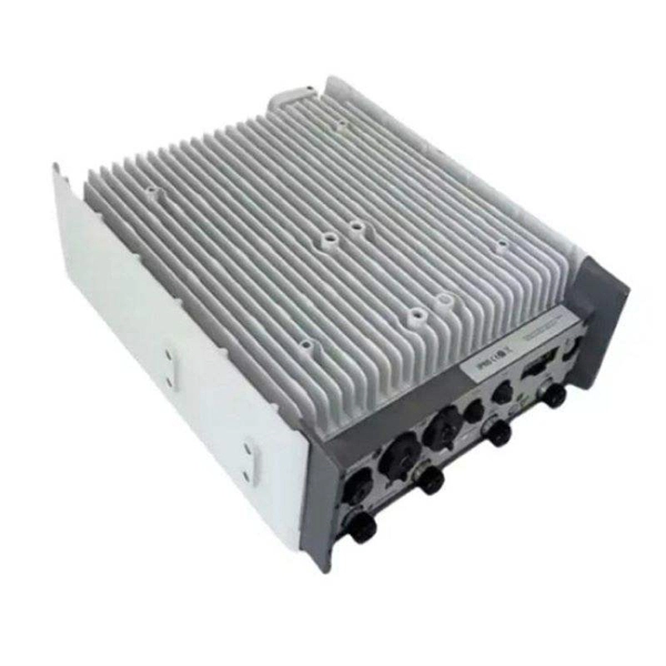
An optical line termination (OLT), also called an optical line terminal, is a device which serves as the service provider endpoint of a. It provides two main functions: 1. to perform conversion between the electrical signals used by the service provider's equipment and the signals used by the passive optical network.
[PDF]
Xero provides everything you need to succeed, from accounting and invoicing to reporting and payroll Just add prices and quantities, and the template will do the maths for you. For more on how to use this quote template, see our how-to guide (we'll send the link along with the. Here you can get over 10 free quotation templates for New Zealand in PDF, Excel, Word & Google Docs / Sheets formats. All the templates can be downloaded, edited and personalized. What is Quotation Template? Quotation template is a standard layout that contains information in a desirable and. Join World Commerce & Contracting for an engaging and interactive session hosted by Statistics New Zealand, where they will explore what this shift looks like in practice. This session brings together voices from across the commercial lifecycle, featuring perspectives from a graduate, team leader. A Proposal and Quotation document is a formal business document used in New Zealand that combines a detailed. business proposal with specific pricing information. Looking for current tenders, RFQs, RFPs & EOIs? Choose a category and/or enter a keyword and we'll show you the opportunites availabalble. For sole traders and small businesses with up to 2 employees. For established businesses needing to fast track pay runs and inventory. Our AI agents will take care of the.
[PDF]
Optical line terminals, also called optical line terminations (OLTs), serve as endpoints for passive optical networks (PONs). They convert electrical signals from equipment managed by a service provider to fiber optic signals readable by a PON. It provides two main functions: to perform conversion between the electrical signals used by the service provider's equipment and the. In the age of fiber-to-the-home (FTTH) and ultra-broadband connectivity, the Optical Line Terminal - or OLT - is one of the most crucial devices powering our high-speed digital world. When you stream a 4K video, join a remote meeting, or play an online game on a gigabit fiber connection, an OLT. At the heart of a point-to-multi-point or passive optical network (PON) is the optical line terminal (OLT). Modern OLTs offer communication service providers (CSP) the ability to launch multigigabit services to tens of thousands of subscribers from a single location or just ten. Whether you are using high-speed internet at home, watching IPTV, or running cloud-based.
[PDF]
Our team of experienced engineers and technicians offers a unique, single-source solution across New Zealand . Our services include: Flexible Locations Pick up and drop off at any of our three sites. Genuine Parts: We use manufactures genuine parts only. At CPS, we provide an extensive range of repairs and service to ensure your test and measurement equipment is restored to working condition. Contact our technical support team to request assistance with your equipment or digital technology. Log a ticket here:. How can we help you? New Zealand (Christchurch Office) All enquiries for Yokogawa Test & Measurement Products are handled by our appointed distributors. Please contact your nearest office. As wholesalers, we deal only with the optometrical professions. Eyeline Optical is a nationally respected optical wholesaler and distributor for over 30 years and is renowned for its expertise, helpfulness, problem-solving ability and friendliness. Eyeline is the largest New Zealand optical. © Copyright 2026 DML Engineering. Powered by Airsquare. Pacific Optics Limited manages its sales distribution through its highly trained and motivated Territory Sales Representatives or to customers specific requirements. All products are distributed either direct.
[PDF]
An optical line termination (OLT), also called an optical line terminal, is a device which serves as the service provider endpoint of a passive optical network. It provides two main functions: to perform conversion between the electrical signals used by the service provider's equipment and the fiber optic signals used by the passive optical network.to coordinate the multiplexing between the conversion. FeaturesOLTs include the following features: • A downstream frame processing means for receiving and churning an cell to generate a downstream frame, and converting a parallel dat. Most vendors integrate an entire fiber optic management system for ISPs to manage OLTs as well as client ONTs and as such are not interoperable. • • BT-PON.
[PDF]

Shop network switches, including PoE, managed, unmanaged, and gigabit switches. Get high-performance connectivity with easy setup, competitive prices, and express delivery. An LPO (Linear Pluggable Optics) solution offers considerable power savings for optical interconnect by removing the digital signal processing (DSP) function from the pluggable optical module. This architecture takes advantage of the capabilities in each segment of the link to form a power, cost. One of the most groundbreaking network innovations driving transformations of data centers in 2025 is Linear Pluggable Optics (LPO)—a Digital Signal Processor (DSP)-free optical solution designed to optimize power, cost, and latency. At Dell Technologies, we are excited to offer fully supported. Upgrade your network with top-of-the-line switches. a wide array of high-performance network switches designed to enhance data transfer, improve efficiency, and ensure seamless connectivity. Linear Pluggable Optics (LPO) has emerged as a promising solution to address this challenge, offering a more efficient way to move data within server racks. Unlike its predecessor, Co-Packaged Optics (CPO), which integrates optical components directly into the electrical package, LPO focuses on. Simple and flexible solutions ideal for IoT deployments and out-of-the-wiring-closet setups. Operates on Cisco IOS Software, offering CLI and web UI for easy device and network management. Fast delivery across.
[PDF]

To use a power meter for fiber optic testing, always clean connectors first with lint-free wipes or click-to-clean tools. Select the correct wavelength and set your reference. You measure optical power in dBm or insertion loss in dB. Consistent procedures ensure accuracy. Verify light travels from. The most basic fiber optic measurement is optical power from the end of a fiber. This measurement is the basis for loss measurements as well as the power from a source or presented at a receiver. Typically both transmitters and receivers have receptacles for fiber optic connectors, so measuring the. An optical power meter measures the strength of light traveling through a fiber optic cable, giving you a reading in dBm (decibels relative to one milliwatt). This article will guide you through the methods, instruments, and key considerations for measuring fiber. Fiber optic cabling is the high-performance core of today's datacom networks. As network speeds and bandwidth demands increase, fiber performance requirements have become more stringent. Fiber testing is more important than ever. An OPM uses a photodiode to generate an electrical current proportional to optical power.
[PDF]

Fiber Optic Welding How To Joint Fiber Optic Cablesplicing fiber optic cable,fiber optic splice,fiber optic,fiber optics,fiber splice,how to splice,fibre opt. The optical fiber connection adopts the fusion splicing method. The whole process is similar to the welding of metal wires, and it is generally carried out by electric isolation. At the moment, there are two methods of connection: Thermal welding of optical fibers consists in bringing the ends of the conductor to melting using a fiber optic splicer, and more specifically - located inside the electrodes. The welded ends are then pressed and a weld is formed. The most work is waiting for installers, whose tasks can be divided into several stages: In this part, we will deal with the second stage, i. welding, which is considered to be one of the most difficult parts of installers' work in. Open the stripping tube and wipe the grease on the optical fiber with toilet paper and alcohol cotton. On the welding disc, make the optical fiber precoil first and cut the optical fiber into an appropriate length to facilitate the coil fiber work after welding. Add heat shrink tube. Procedure. Another method is to use the so-called mechanical welding. It uses special parts that are prepared in advance to connect the two ends. Thanks to this, you can connect two ends of the cable with a ready-made splice, without the need to use an optical fiber splicer. While this method may appear to be.
[PDF]

Convenient Supply Solutions for Oscilloscope Probes Products for resellers and dealers based in Uzbekistan serving Tashkent, Namangan, Samarkand, Andijan, Bukhara, Nukus, Qarshi, Kokand, Chirchiq, Fergana and more. Lenses made from all optical glasses, including Si, CaF2, Ge, ZnSe, ZnS, quartz, and sapphire: Standard lenses in all common designs as well. Optical surface inspection detects minimal defects. This way, you produce your workpieces with consistently high quality. com is a proven supplier of Oscilloscope Probes products dealing major product. According to Volza's Optical,Instrument Import analytics, 698 verified Optical,Instrument buyers in Uzbekistan have imported Shipments from 661 global suppliers. OOO HILBRO accounted for 51% of Uzbekistan's total imports with (1,143 shipments). IP OOO. Compare products based on your own technical specification criteria. How does our search work? With MEET OPTICS search you get direct access to our database of thousands of optical components from providers worldwide. Prices and product specifications directly listed from optical component. Copyright © 2022 GOC-UZ. See our terms of use and privacy policy. Find and discover Optical Equipment buyers & importers for all products in Uzbekistan, featuring details on their shipment activities, trade volumes, trading partners, and more. Subscribe to global trade data intelligence to.
[PDF]

Wavelength measurement devices work on the principle of measuring the distance between two consecutive points of an electromagnetic wave in terms of wavelengths. This can be achieved through various methods, including spectrophotometry, interferometry, or the use of optical spectrum. These devices accurately determine the wavelength of light, providing crucial information for research, quality control, and diagnostics. Wavelength is a fundamental property of light and can significantly affect its interaction with matter. Precise wavelength measurement allows scientists to. Wavelength meters are interferometers used to measure wavelengths of laser beams. The devices are mounted on benches or desktops. They generate numerical values identifying pulsed and continuous wave lasers. They enable. This article provides a comprehensive explanation of the concept of wavelength in physics, particularly in optics and photonics. It defines wavelength as the spatial period of a wave, explaining its mathematical relationship to the wavenumber, optical frequency, and phase velocity. Accurate wavelength measurement is crucial in fields like physics, chemistry, astronomy, and engineering. Each method offers unique insights and varying degrees of precision.
[PDF]

Match trench method with the correct underground fiber structure (GYTS, GYTA53, GYTY53, micro-duct). Control pulling tension and bend radius – most damage happens during installation, not operation. Plan depth, backfill and warning markers early to reduce maintenance risk and. ion) and “ Installed” (after installation). The following formulas may be used to determine general guidelines for installing Corning Optical Communications fiber optic cable; however, refer to the cable specifi simply double the minimum working bend radius. Split cable guides and split 40-in. 1. 01 This best practices procedure provides general information for the installation of fiber optic cables in direct buried applications. The methods described are intended for guideline use only, as it is impossible to cover all the various conditions that may arise during an installation. Individual. Fiber optic cable transmits data as pulses of light through thin strands of glass, offering superior bandwidth and distance capabilities compared to traditional copper wiring. Direct burial is a common and highly effective method for external installations. ■ 1). Conventional trenching is suitable for open areas, while narrow trenching or horizontal directional drilling (HDD) is often preferred in urban or high-traffic environments to minimize disruption during underground fiber optic cable installation. Using Conduits to Protect Underground Fiber Cables In.
[PDF]

Per‑unit estimates often appear as $0. 50 per ft for basic fiber plus additional charges for trenching and install labor. Several drivers shape fiber installation pricing. Homeowners and businesses typically pay for fiber optic cable installation based on distance, conduit needs, and labor. The main cost drivers include material type, run length, trenching or aerial work, and any required permits or inspections. This guide provides clear cost estimates, price ranges. The initial cost of installing fiber optic cables can vary depending on the chosen installation method and specific project requirements. Total Project Costs: For commercial installations, expect costs ranging from $5,000 to $20,000 per mile for underground projects and from $40,000 to $60,000 per. Buyers typically pay for fiber laying by combining material costs, labor time, and permitting plus trenching or aerial support fees. A short residential drop under 1,000 ft may cost $3,000-$8,000, while longer runs to an attached garage or street node can run $8,000-$25,000. The price often reflects project scope, geography, and local regulations, making. Fiber optic cable costs vary widely – from $0. Installation can be more expensive than the cable itself, especially with site challenges.
[PDF]

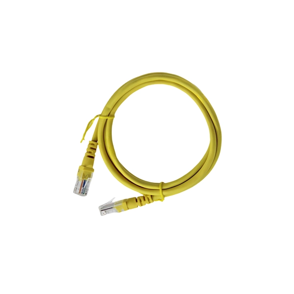
This article provides a detailed technical comparison between fiber optic and copper cables, offering a clear perspective for engineers, network architects, and procurement managers. The core distinction between the two technologies lies in the physics of data. There are significant differences in performance between ADSS cables (all-dielectric self-supporting optical cables) and traditional optical cables, which are mainly reflected in the following aspects: 1. This type of fiber optic cable is designed to support its own weight without the need for additional support structures like messenger wires. The ADSS. There are several factors to assess when deciding which cable type is right for your application, including speed of connection for new customers, ease of changes and repairs, installer certification requirements, and the ability to expand the network over time. ADSS Fiber Optic Cables are a type of optical fiber cable designed specifically for. All-dielectric self-supporting (ADSS) cable is a type of optical fiber cable that is strong enough to support itself between structures without using conductive metal elements. It is used by electrical utility companies as a communications medium, installed along existing overhead transmission.
[PDF]

This practical file details experiments conducted in Optical Fiber Communication, covering modulation techniques, system components, and performance analysis. An optical fiber is a glass or plastic fiber designed to guide light along its length, widely used in fiber-optic communication, which permits transmission over longer distances and at higher data rates than other forms of communications. Fiber-optic communication is a method of transmitting. Availability of plastic optical fiber (POF) The plastic optical fiber used in some of these experiments is available for science distributors. It is a 1000micron (1mm) POF available from several suppliers. FOA has samples available at no cost for teachers at schools in the US. Key experiments include amplitude modulation, frequency modulation, and pulse width modulation, aimed at understanding fiber optic systems. This document summarizes 10 experiments on optical fiber communication: 1. Studying a 650mm fiber optic analog link and the relationship between input and received signals. Optical fiber communication Laboratory Optical fiber communication Laboratory List of Experiments: 1. To set up a analog optical fiber link 2. To measure the characteristics of LED and LASER 5. Tech curriculum designed to provide a comprehensive understanding of optical fiber communication systems. This lab offers an immersive, web-based simulator that enables you to explore and experiment with key concepts in optical.
[PDF]

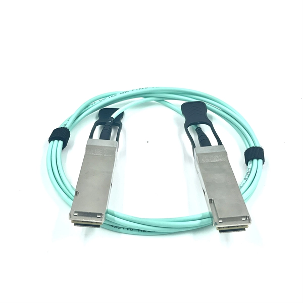
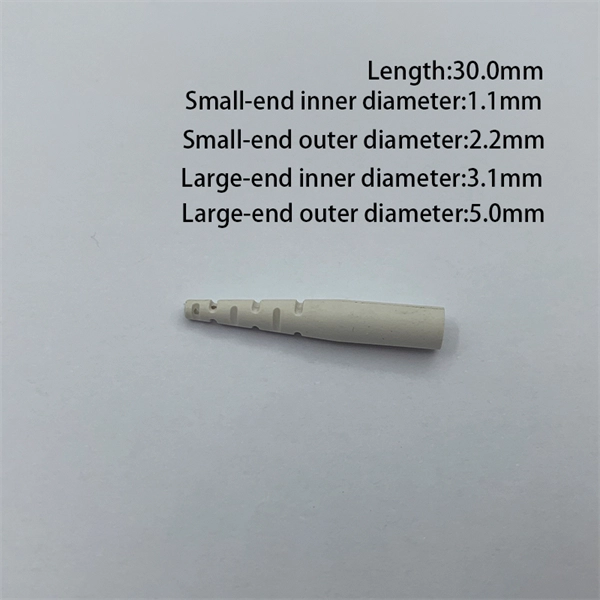
The optical module is usually composed of Transmitter Optical Subassembly (TOSA, containing a laser LD Chip), Receiver Optical Subassembly (ROSA, containing a photodetector PD Chip), a driving circuit, and an optical and electrical interface. Its schematic is shown in. This section explains the structure of a typical pigtail butterfly module, which gets its name from the two rows of seven leads at right angles on each side of the metal package plus an optical fiber pigtail at one end (Fig. Let's look at the internal structure (Fig. 2) of a common butterfly. Optical modules are devices used to connect network devices, transmit and receive data between network devices, and can be used to convert optical and electrical signals. The optical module is a very important component in an optical communication system. Optical devices are the core components of optical modules. TOSA and ROSA in Common Optical Transceiver Modules For ordinary optical transceiver modules, there are two optical devices, TOSA and ROSA, which have opposite effects.
[PDF]