A good laser source for a singlemode link will have a power output of ~ +3 to +6 dBm - 2-4mw - coupled into the fiber. Tx power (transmission power) refers to the intensity of the optical signal output by the transmitting end of the optical module. However, in practical use, we adopt the average Tx power. These modules, including SFP, SFP+, and SFP28, are widely used in enterprise networks, data centers, and carrier-grade deployments. Optical loss is measured in “dB” which is a relative measurement, while absolute optical power is measured in “dBm,” which is dB relative to 1mw optical power Loss is a negative number (like –3. 2 dB) while power measurements can be either positive (greater than the reference) or negative (less than. SFP (Small Form-Factor Pluggable) modules are compact transceivers that allow for high-speed communication between network devices. They are essential in applications like telecommunications, data centers, and enterprise networks. Generally, the power levels are specified in terms of transmit (TX) power and. Transmit power is the power at which the transmitter of an optical transceiver module transmits optical signals in dBm. When the signal received is outside of the range, there is a.
[PDF]

The core measurement procedure follows five steps: Turn on the meter and let it warm up. Most meters need a brief stabilization period before readings are reliable. Check your model's manual, but a minute or two is typical. Set the wavelength to match your light source. Fiber loss is the difference between the power when light is coupled from the transmitting end to the fiber and the power when the light reaches the receiving end. Generally speaking, when measuring the. An optical power meter measures the strength of light traveling through a fiber optic cable, giving you a reading in dBm (decibels relative to one milliwatt). The basic process is straightforward: turn the meter on, set it to the correct wavelength, clean your connectors, plug in, and read the. A power meter and light source are essential test tools that work in tandem to measure fiber optic cable loss and evaluate the quality of optical links. They provide the data necessary to quantify signal loss and pinpoint issues that could impact network performance. Here's how they work: A power. You measure optical power in dBm or insertion loss in dB. Verify light travels from transmitter to receiver. We'll give you the basic information you need and provide some printable references.
[PDF]

Key finding: This paper develops analytical models and design procedures of ultra-wideband Wilkinson power dividers using linearly tapered transmission lines (TTLs) which provide size reduction and broadband performance. Read more. Power dividers are the passive electronic equipment used for splitting the power. They are now being employed in a variety of communications applications such as telephonic, antennas configurations, mobile connectivity, internet technology, & optics, etc. They come up with very low loss, operate at. RF and microwave power splitters and dividers create two copies of the same signal, while ideally preventing crosstalk between the outputs. Doing this with minimal loss while maintaining signal integrity is a challenge. In this article we explain how power splitters work and what the tradeoffs are. The rise of wireless connectivity requirements for applications such as Internet of Things (IoT), cellular, and automotive electronics is resulting in systems that are increasingly using RF signals, components, and subsystems. Often, designers need to direct these signals to more than a single. A power divider is a passive electronic device used in radio frequency (RF) and microwave applications to split an input signal into multiple output signals with equal or specified power levels, while maintaining impedance matching to minimize signal reflection and loss. How can power dividers.
[PDF]

Uses 12 wavelengths derived by shifting 6 traditional CWDM wavelengths left and right (±3. 5nm) using temperature tuning. Balances cost and channel density. Applications: Primarily 5G mobile fronthaul and midhaul networks requiring moderate capacity and cost efficiency. In fiber-optic communications, wavelength-division multiplexing (WDM) is a technology which multiplexes a number of optical carrier signals onto a single optical fiber by using different wavelengths (i., colors) of laser light. This technique enables bidirectional communications over a. This is the complete guide to Dense Wavelength-Division Multiplexing (DWDM) wavelengths and channels in 2024. Then, you will enjoy this new complete DWDM wavelength channels guide. What are the benefits of DWDM? #3. DWDM and CWDM enable carriers to deliver more services over their existing fiber infrastructure by combining multiple wavelengths on a single fiber. But navigating the alphabet soup of CWDM, DWDM, MWDM, LWDM, and SWDM can be daunting. 5 nm (800 GHz) in the O-band of 1270–1330 nm by using x-cut lithium-niobate-on-insulator (LNOI) photonic waveguides for the first time.
[PDF]
These products are highly integrated, compact in size, structurally compact, safe and reliable in operation, easy to maintain, and portable. In distribution systems, they can be used in ring network distribution systems as well as in dual power supply or radial terminal distribution. High voltage and low voltage complete sets occupy a significant place in modern electrical engineering as they are responsible for safe, secure, and efficient power distribution to all types of industries. They are known as complete switchgear assemblies because they integrate inside them such. Electricity plays a critical role in ensuring national well-being and livelihoods, and the stable development of the power industry drives socio-economic progress. To achieve structural adjustment and transformation in the power industry, the foremost priority is enhancing the performance of. Our high and low voltage complete electrical equipment solutions are designed based on a deep understanding of the current development trends in the power industry and accurate predictions of future power demand. It is mainly used to protect, control and isolate electrical equipment. Its primary functions are to cut off the power supply of equipment to facilitate subsequent maintenance. Senior Electrical Engineer, with 12 years of experience in high and low voltage switchgear installation, commissioning, and overseas project technical support. Currently, Thor is the Technical Department Manager at Weisho Electric Co.
[PDF]

The operation and skills of fiber optic fusion splicing technology can be mainly divided into five steps: fiber stripping, fiber cutting, fiber melting, fiber sleeve, and fiber winding. Two types of splices are used in fiber optic cabling one is Mechanical the other is Fusion. And tools used for fiber fusion: fusion splicer; fiber cleaver; cable stripper; fiber optic stripper; alcohol;. These specialized devices are engineered to manipulate, terminate, join, and verify light-carrying strands without introducing microscopic fractures or contamination. At Weunion, we categorize these essential instruments into four primary operational phases: Preparation: Removing protective layers. Various techniques can remove the coating: Regardless of the method used to strip the coating, it is important to use the correct tools and techniques to prevent damage to the bare glass. Ensuring the fiber. What is Fiber Optic Splicing and Why is it Needed? – #1. Use and Maintain Your Cleaver Correctly – #3. Set Your Fusion Parameters in a Systematic Way What is Fiber Optic Splicing and Why is it Needed? First, let us understand the meaning of the term. Fusion splicing joins two optical fibres end-to-end using heat, creating a seamless connection for minimal signal loss. owever, proper cable preparation is essential before firing up your fusion splicer. A poorly prepared fibre can lead to weak splices, high attenuation, or complete failure.
[PDF]

Typically used in power substations and industrial plants, these high voltage (HV) switchgear devices are designed to withstand high voltage levels and provide protection against power surges and short circuits to transmit electricity ove. Typically used in power substations and industrial plants, these high voltage (HV) switchgear devices are designed to withstand high voltage levels and provide protection against power surges and short circuits to transmit electricity over long distances. RESA Power partners with large industries to engineer and maintain the health of these compone. Low voltage (LV) switchgear plays a critical role in the safe, efficient, and reliable delivery of electricity with voltage rankings up to 1kV. RESA Power understands these components are the backbone of every operation in your business with common uses of LV switchgear in commercial applications including: powering motors, air conditioners, heater. Medium Voltage (MV) Switchgear is a fundamental component that helps safeguard electrical systems with voltage rankings between 1kV and 38kV. RESA Power is a proud distributor and manufacturer of a variety of switchgear styles including metal-clad, metal-enclosed, pad-mounted, and more. Common uses of MV switchgear systems are found in medium to la.
[PDF]
State Grid Corporation of China was established on December 29, 2002, as a state-owned sole proprietorship company directly managed by the central government under the Company Law. Many public transport operators like RATP Group (top) and Amtrak (bottom) are considered state-owned enterprises. With a registered capital of 829. 5 billion yuan, its core business is investment, construction, and operation of power. See Q2-Q7 to understand if your product is considered an iron or steel product, construction material, or manufactured product and what “produced in the United States” means for each of these product categories. Infrastructure projects are defined very broadly to include any activity related to the. The lead author for this document is Lisa M. Benson, Strativia, under contract to the Standards Coordination Office of NIST. Additional guidance, initial research, and review of the document were provided by the staff of the Standards Coordination Office of NIST including: Mary Donaldson, Gordon. Electrical is addressed in specific standards for general industry and maritime. This section highlights various OSHA standards and documents related to electrical hazards. Visit the Electric Power Generation, Transmission and Distribution Standard Page for information on the final rule.
[PDF]

Learn how to monitor SFP optical power on Cisco switches, interpret Tx/Rx levels, and troubleshoot fiber link issues. Step-by-step CLI commands, model-specific guidance, and best practices included. In this article, we will break down the key factors influencing TX/RX power, explain how to calculate the optical power budget, and provide actionable insights for optimizing your network's performance using SFP modules. SFP (Small Form-Factor Pluggable) modules are compact transceivers that allow. SFP (Small Form-factor Pluggable) optical modules are compact, hot-pluggable transceivers that enable network equipment to connect seamlessly to fiber and copper links. Even if an interface appears up, degraded Tx/Rx levels can cause intermittent flapping, packet loss, or err-disabled states. Think of it as the “translator” for your network equipment, converting electrical signals into optical signals. The most two important factors of the SFP transceiver: Output power (TX power) and receiver sensitivity (RX sensitivity). The optical TX power is the signal level leaving from that device, which should be within the transmitter power range. The RX sensitivity is the incoming signal level being. In current network communication, SFP optical modules are an indispensable physical foundation for building network channels. They form high-speed channels for optical signal transmission. Therefore, to ensure their.
[PDF]

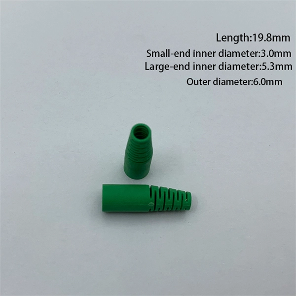
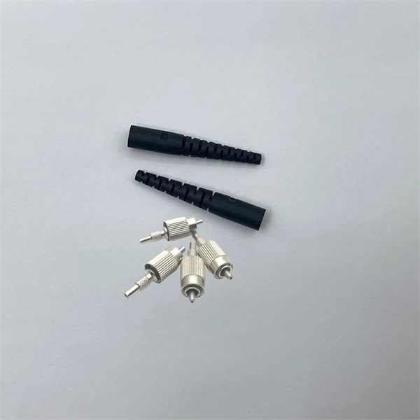
Product Features: Square protective box, suitable for skin cable and leather cable tight protection 6cm in length of skin heat shrink tube welding protection. A close connection between the leather cable and pigtail. Looking for specific info?. *In the era of high bandwidth, reliable fiber optic power equipment is particularly important. This handheld photometer can help check cable performance, calculate relative power loss, locate faults, and troubleshoot. *Measure the length of network cables, coaxial cables, and telephone cables. Able. Usually ships within 3 to 4 weeks Click here for details of availability. Able to test open, short, cross-connect, See more product details TABKER 4000667180167 3 x 2 x 1. Check each product page for other buying options. Price and other details may vary based on product size and color. Need help?. power across any given fiber. This document will serve as an overview of the major features and functions of the device and will ofer tips for trouble shooting com on issues in optical networks. If you are looking for a low cost device capable of saving and reporting take a look at the RP460 or. ments to the instrument's performance and functionality. The figures given in this manual ion of this manual to ensure the accuracy of its contents. However, should you have any questions or fi gistered users with a variety of information and services. Please allow us to serve you best by.
[PDF]
In addition to ultra-fast signalling, the deployment of a high-Tg EO polymer in the SPH modulator allows for high-temperature operation without failure, which is essential for improving the datacentres' energy e.
[PDF]

This standard covers the construction, mechanical, electrical, and optical performance, installation guidelines, acceptance criteria, test requirements, environmental considerations, and accessories for a nonmetallic, all-dielectric self-supporting (ADSS) fiber optic cable. An All-Dielectric Self-Supporting (ADSS) cable operates without metallic messengers, relying entirely on its aramid yarn strength members. For a typical 12-fiber ADSS cable with a 8. AFL-ADSS® (All-Dielectric Self-Supporting) cable is ideal for installation in distribution as well as transmission environments. This guide provides general recommendations for the selection of methods, equipment, and tools for the stringing of ADSS (All Dielectric Self-upporting) fiber optic cables including short and Long Span ADSS cables. The installation methods for ADSS cables are essentially the same as those used for. This Installation Manual is a recommendatory installation document provided by HANGZHOU ZION COMMUNICATION CO. The installation manual is established based on the newest issued international standards such as lEEE Std 1222: 2004, "lEEE standard for all-dielectric. Round aramid reinforced ADSS cable for intermediate and long spans, 4 – 96 fibres. VDE: A- DF 2Y (ZN) 2Y This specification covers a family of optical cables with 4 - 96 fibres for intermediate and long spans.
[PDF]

It consists of 5 buttons. A power button, a button to turn on the VFL, a lambda button to set the wavelendth, a REF button, and a dBm/W button to set the unit of power. First, you check the initial power of a light signal. Then you check its power at the other end of optical. OPM interface: insert the fiber to be tested, test the optical power. REF/dB key: Short press the dB to switch unit, click once nW/dBm/dB to enter the upper clear data, press and hold until REF is displayed on the screen, and set the current optical power as reference value, enter the relative. There are two buttons on this meter. One is the power button, used to turn the meter on/off. At the top, there is a sensor that detects the light beam. The. at -22 (or 25 with tone on)). To do this you. Active Equipment Power Measurement Fiber Continuity Patch Cable Testing Check MM Reference Cables - Dual OWL MM Sources Check MM Reference Cables - WaveSource MM Sources Check SM Reference Cables - Laser OWL SM Sources Check SM Reference Cables - WaveSource SM Sources. Power-off: Press and hold “MODE” key for 2 seconds or more until “OFF” displays on the screen. Note: This instrument will shut down automatically without receiving any operation instruction for 10 minutes. Function selections: It.
[PDF]

Our product meets the specification of Cisco® QSFP56-200G-SR4 and we proudly offer a compatibility guarantee and limited lifetime warranty. Carritech Optics delivers high-performance 200G Transceivers designed to provide ultra-fast, scalable, and efficient connectivity for data centres, cloud networks, and telecom operators transitioning to next-generation infrastructures. Unlocking hyperscale and 5G network performance with 200G. QSFP56-200G-SR4 Cisco® Compatible Transceiver QSFP56 200GBase-SR4 (850nm, MMF, 100m, MPO, DOM) ATGBICS Cisco® Compatible QSFP56-200G-SR4 QSFP56 200GBase-SR4 form factor network transceiver supports a distance of up to 100m over multi-mode fibre (MMF) using a wavelength of 850nm via an MPO-12. Worry-Free 30 Day Returns ( Return shipping cost on us) 5-Year warranty (Exchange New) & Lifetime warranty (Repair) Free Trial & Bulk Price Available Late Shipping till 8pm. 5-YEAR WARRANTY Lifetime warranty for repair. 30-Day Money-back Guarantee. Designed in compact form factors such as QSFP56 and QSFP-DD, these transceivers support 200G. Discovery's Coherent Optical Receivers are designed for 100 Gb and upcoming 200 Gb and 400 Gb fiber optic communication systems. Optical Dual Polarization QPSK (DP-QPSK) and 16 QAM modulation formats are detected and converted to electrical signals that can be fed to a digital storage scope, or. Copyright © Chengdu Superxon Communication Technology Co.
[PDF]

10Gtek's QSFP56 200G transceiver module is designed for use in 200 Gigabit Ethernet links over 2Km single mode fiber. The module has 4 independent electrical input/output channels operating at 26. Pricing (USD) Filter the results in the table by unit price based on your quantity. A tariff of 6% may be applied if shipping to the United States. This transceiver consist a transmitter/receiver unit operating on a set of 4. Cisco Compatible 200GbE SR4 transceiver is a 4-channel, pluggable, QSFP56, optical transceiver designed for use in 200GbE Ethernet applications. NADDOD's 200GbE SR4 QSFP56 transceiver that operates over a 4-lane parallel multi-mode fiber (MMF), via a standard MPO-12 UPC connector. Each. QSFP56-200G-SR4 Cisco® Compatible Transceiver QSFP56 200GBase-SR4 (850nm, MMF, 100m, MPO, DOM) ATGBICS Cisco® Compatible QSFP56-200G-SR4 QSFP56 200GBase-SR4 form factor network transceiver supports a distance of up to 100m over multi-mode fibre (MMF) using a wavelength of 850nm via an MPO-12. 10Gtek's QSFP56 200G transceiver module is designed for use in 200 Gigabit Ethernet links over 2Km single mode fiber. Single-mode fiber optical reference transmitter enables 200G-per-lane design validation and 400G-per-lane research. Find out what's included and explore available upgrade options from Keysight. The Keysight N7718C optical.
[PDF]