NOTE: Insert the end of a colored wire into one of the holes in a butt connector. With the wires pushed tightly against the far inside wall of the connector, squeeze the red button until it depresses. The OS-8171 Beam Splitter is designed to be used with the OS-8170 Brewster's Angle Accessory and the OS-8539 Educational Spectrophotometer System. ) In the Brewster's Angle experiment, the Beam Splitter is used with a. am Splitters/Combiners. This document describes this product line, as well as general operation guidel into two output beams t beams of equal power. The standard product is designed for use in the visible spectrum 400-700 nm wavelength). Custom Surgical Beam Splitter sends 50% of the light to the eyepieces and 50% to the smartphone camera. If you want to understand more about how beam splitter works, watch the video below. It is not necessary to. As title. in your towing vehicle manual. Be sure the hitch is installed onto the vehicle. Releasing the pin before will cause supp owards the engine faster than you can let go. This is because if a fire. Meadowlark Optics presents its VersalightTM wire grid polarizing beam splitters. Manufactured for wavelength ranges between 420 and 2600 nm, this polarizer is ideal for broadband and wide field-of-view applications. Wire grid polarizing beam splitters are manufactured out of our Versalight wire.
[PDF]

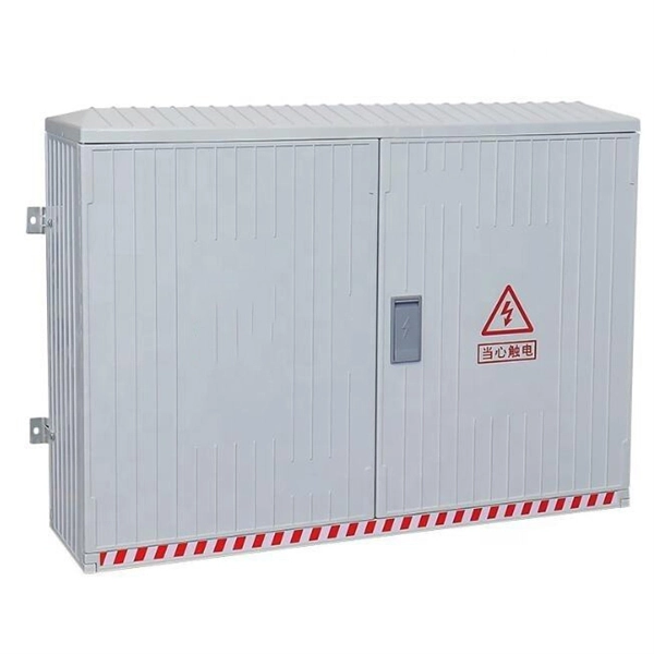
This video shows real on-site footage of electrical installation, demonstrating safe and standardized wiring methods used by professionals. more Learn how to wire a distribution box step by step! This video shows real on-site footage of. Material preparation: Prepare the required circuit breakers, wires, wiring ties and other materials, and ensure that they meet the design drawings and installation requirements. Location determination: Determine the installation position of the circuit breaker according to the position of the. Learn how to install a distribution box safely and correctly. Covers wiring, placement, standards, and expert tips for a compliant setup. A distribution box is the heart of any electrical system. It takes the incoming power and safely distributes it to different circuits throughout your building. And all the switching and protective devices are installed in the distribution box. Single Phase Distribution Box generally consists of Double Pole MCBs, Single Pole MCBs, and RCCBs. So here's what you need to know about wiring distribution panels, to make sure yours operates exactly as needed and as expected. Each circuit supplies a specific load, whether it's going to. Explosion-proof distribution boxes, vital terminal distribution equipment in power systems, play a crucial role in controlling and protecting industrial electricity in hazardous environments.
[PDF]

A double switch box allows you to control two separate electrical circuits or devices from a single location. This can be useful in situations where you want to control different lights or appliances independently. Here is a step-by-step guide on how to wire a double switch box:. Connecting two electrical boxes together is a relatively simple job, but there are some important steps that must be taken to ensure it's done safely and correctly. From adding junction boxes to selecting the right wire gauge, the following steps will help guide you in installing an electrical. A double switch box, often called a double gang box, is a rectangular enclosure designed to house two electrical devices, such as two single-pole light switches. Before beginning any electrical work, safety is the. We're diving into some essential 'electrical wiring' in this video, focusing on how to properly set up an wireing a'electrical box' with a three way and single pole light switch. more Audio tracks for some languages were automatically generated. Learn more Unbelievable Trick to. This page contains wiring diagrams for two outlets in one box. Included are arrangements for 2 receptacles in one box, a switch and receptacle outlet in the same box, and 2 switches in the same box. Whether you want to control two lights from one location or two separate devices from the same switch, a double switch box is a versatile solution.
[PDF]

This video shows real on-site footage of electrical installation, demonstrating safe and standardized wiring methods used by professionals. more Learn how to wire a distribution box step by step! This video shows real on-site footage of. Understanding the wiring diagram of an electrical panel box is essential for electricians and homeowners alike, as it allows them to troubleshoot any electrical issues, carry out repairs, or make additions to the system. The electrical panel box wiring diagram provides a visual representation of. A distribution box, also known as an electrical distribution board, is a critical component in electrical systems. It serves as a central point for distributing electricity to various circuits in a building or facility. This section will explain its function, types, and the importance of correct. Understanding how to safely set up the main connections of a home's power distribution system is essential for ensuring reliable and secure operation. A correct installation process minimizes the risk of electrical faults and increases the longevity of your setup. Proper knowledge is crucial for. Material preparation: Prepare the required circuit breakers, wires, wiring ties and other materials, and ensure that they meet the design drawings and installation requirements. Whether you're an electrician or a DIY enthusiast, this guide will help you understand the basics of home electrical distribution. What is Distribution Board? Distribution board.
[PDF]
In this video, we'll walk you through the process of wiring a home distribution box with a detailed connection diagram. Whether you're an electrician or a DIY enthusiast, this guide will help you understand the basics of home electrical distribution. more Welcome to. This guide provides step-by-step instructions for connecting a distribution box and highlights key factors to consider during installation. What Is a Distribution Box? A distribution box, also known as an electrical distribution board, is a critical component in electrical systems. A distribution board or distribution box is where the main power supply is distributed to multiple loads. In this article, I'll teach you how to wire a Power Distribution Block (PDB) to distribute electricity from a single input source to multiple pieces of equipment in your branch circuit.
[PDF]

This video shows real on-site footage of electrical installation, demonstrating safe and standardized wiring methods used by professionals. more Learn how to wire a distribution box step by step! This video shows real on-site footage of. Connecting a distribution box involves several steps to ensure proper electrical flow. Follow this guide for a clear and safe connection process: Before starting, always ensure the main power is turned off to avoid electrical shock. Fix the box securely to the wall, ensuring it's at an accessible. An electrical panel box, also known as a breaker box or a distribution board, is a crucial component of any electrical system. It serves as a central hub for distributing electricity throughout a building, ensuring that power is delivered safely and efficiently to all the required locations. In this guide, we'll break down everything you need to know to install a distribution box correctly and confidently. Choose the right box based on environment (indoor/outdoor), load capacity, and durability. Check for proper IP/NEMA ratings and material quality. Whether you're an electrician or a DIY enthusiast, this guide will help you understand the basics of home electrical distribution. Material preparation: Prepare the required circuit breakers, wires, wiring ties and other materials, and ensure that they meet the design drawings and installation requirements. Location determination:.
[PDF]

Step-by-step guide on connecting an inverter to your distribution board for uninterrupted power supply. The process begins with turning off the main power supply to ensure safety. Next, choose an inverter with a suitable capacity to handle your power needs, ensuring it matches the. In this article, you will find information about connecting inverter to distribution box: essential safety tips, step-by-step guidance, and common mistakes that often lead to inverter failure, so that you can avoid them. Last Updated on September 17, 2025 by June The most extensive use of inverter. Connecting an inverter to a distribution board allows you to harness stored energy from batteries or solar panels for powering electrical devices in your home. This setup provides backup power during outages and can also contribute to energy savings by utilizing renewable energy sources. This guide. In this video, we'll guide you through the process of wiring a UPS (Uninterruptible Power Supply) or inverter for your home or office. By following a few simple steps, you can easily learn how to connect an inverter DB wiring diagram. Connecting an inverter DB wiring. Scroll to the bottom of any page to find a sun or moon icon to turn dark mode on or off! I'm not an electrician and do not want to screw this up. What type of wiring do I need to connect the inverter to the distribution box? I have a 1*60A 4*20A FL+LS distribution box with a Sungold Power 5000W 48V.
[PDF]
Learn how to install a distribution box safely and correctly. Covers wiring, placement, standards, and expert tips for a compliant setup. It takes the incoming power and safely distributes it to different. In this video, we'll walk you through the process of wiring a home distribution box with a detailed connection diagram. more Welcome to our channel! In this video. Single Phase wiring installation is the most common wiring in residential buildings. In Single Phase supply (230V in UK, EU and 120V & 240V in the US & Canada), there are two (one is Line (aka Phase, Hot or Live) and the other one is Neutral) incoming cables from the utility poles to the kWh energy. The electrical service panel, often called a breaker box, acts as the central distribution point for all electricity entering a home. An electrical panel box, also known as a breaker box or a distribution board, is a crucial component of any electrical system. It serves as a central hub for distributing electricity throughout a building, ensuring that power is delivered safely and efficiently to all the required locations. And all the switching and protective devices are installed in the distribution box. Single Phase Distribution Box generally consists of Double Pole MCBs, Single Pole MCBs, and RCCBs.
[PDF]

This is a simple video showing how to install a 850nm fiber optic link using SFP transceivers between 2 10 Gigabit backbone switches. Covers transceiver inst. As a leading provider of fiber optic solutions, Weunion offers a wide range of SFP-compatible products, including optical transceivers, DAC/AOC cables, LC patch cords, and MPO/MTP assemblies. This guide explores the essentials of SFP connectivity, installation best practices, and how Weunion's. These transceiver modules are hot-swappable input/output (I/O) devices that plug into 100BASE, 1000BASE and 10GBASE ports (for SFP+), which connect the module port with the fiber-optic or copper network. This document contains these sections: The SFP transceiver modules are hot-pluggable I/O. An optical module is an optoelectronic conversion device that transmits data by converting electrical signals into optical signals. Common types of optical modules include SFP, SFP+, SFP28, QSFP, QSFP28, etc. Different types of optical modules have different performance parameters such as speed. The 1310 nm WWDM solution, 10GBASE-LX4, requires the use of a mode-conditioning patch cord on multimode fiber to achieve its specified range of operating distances. more Audio tracks for some languages were automatically generated. Learn more This is a simple. One of the most widely deployed optical solutions for short-distance 10G links is the multimode SFP+ transceiver, commonly referred to as a 10GBASE-SR module.
[PDF]

In today's video, we'll be unboxing the 9-Port Power Supply Box and demonstrating how to connect the cables to provide power to CCTV cameras. A CCTV power supply box sends power to all your cameras from one place. It helps keep things neat and makes your system easier to manage. In this guide, you'll learn how to install it step by step, choose the right type, avoid common problems, and keep your system running safely. Power supply boxes for CCTV are typically used in multi-camera installations instead of using single power adapters for each camera. The process is almost exactly the same if you. Installers of surveillance systems may simply control the power to various CCTV cameras using a CCTV power supply box, also known as a power distribution box (usually at the location of the DVR). This enables a cleaner camera installation. Surge protection can be accomplished in two ways. The power supply box is specifically used to transfer power requirements for all cameras plugged in on the system, to work. Security cameras use RG59U coax siamese wire or CAT5e networking cable to transmit video. Whether you are installing a power box for a new or existing camera system, it is important to understand how to connect cameras to a CCTV Power Supply Box. DC current is polarized meaning it has two leads, a.
[PDF]

The maximum distance of copper is around 328 feet (100 meters), which is a far shorter range than is offered by either of the fiber optic cable types. This is because fiber optic cable is not affected by attenuation, dispersion, or EMI in the same way that copper is. Many factors decide the fiber cable distance, but the key factors include the below six aspects. Attenuation First is the attenuation of the optical fiber. For some. Fiber optic cable transmission distance is determined by two primary physical factors that affect signal quality as light travels through the fiber medium. The selection of fiber optic cables over copper wires or vice versa depends on factors such as bandwidth, distance, and cost of transmission. Fiber optic cables transmit data using light waves, enabling higher. Fiber optic cables have revolutionized modern communication networks by enabling blazing-fast data transmission across vast distances. However, fiber cable runs are not limitless. However, fiber optic cable performance. Q: Is there and electromagnetic interference with optic cables? A: The fiber is glass and the cable is plastic, neither of which are affected by electromagnetic interference. There is a cable used in electrical transmission lines called OPGW- optical power ground wire - that has fiber inside a wire.
[PDF]
In this blog, we will explore the step-by-step process of using a beamsplitter cube effectively, along with some common applications that benefit from this powerful optical tool. Step-by-Step Guide on Using a Beamsplitter Cube. 📦 For purchasing, use the RP Photonics Buyer's Guide for beam splitters. It provides an expert-curated supplier directory, buyer-focused technical background information, and structured selection criteria to support professional procurement decisions. What are Beam Splitters? A beam splitter (or. An Optical Beamsplitter is an optic or optical device that is used to split a beam of light in two. Newport offers a wide variety of Beamsplitters in various shapes. It is a crucial part of many optical experimental and measurement systems, such as interferometers, also finding widespread application in fibre optic telecommunications. One beam is typically reflected while the other is transmitted. The ratio of reflected to transmitted light can vary based on the design of the beam splitter. Our plate beamsplitters have a coated front surface that determines the beam splitting ratio while the back surface is wedged and AR coated in order to minimize ghosting and interference effects.
[PDF]
This video will show you how to wire a Painless Performance headlight relay into your OBS Chevy / GMC truck or Tahoe to keep the low beams on when you run the high beam lights for much better light coverage in night driving conditions. more. If your headlights suddenly seem too high, too low, or uneven, you likely need to adjust the beam pattern on your headlights. In many cases, poor headlight aim comes from extra weight in the rear of the vehicle. For example, a loaded trunk, hunting gear, tools, or a trailer can push the back end. When we want to replace and upgrade our car headlights, we will pay attention to their brightness and beam pattern. But there is one important factor that is often overlooked - the cutoff line. You can. A blown out low beam bulb can make it difficult to see at night and driving with your high beams on all the time can make it difficult for other drivers to see. Fortunately, fixing a bad low beam is a straight forward process in the majority of vehicles that can be done by most people without just. This DIY will explain how to hookup your DRL's to stay on with your low beams WITHOUT running a switch in the cab. One 30 amp max fuse holder 5. Length of assorted color 14-16 guage wire 6. Female connectors (blue) 7. The right pattern illuminates potential hazards, complies with legal standards, and ultimately keeps you safe. more Audio tracks for some languages were automatically.
[PDF]

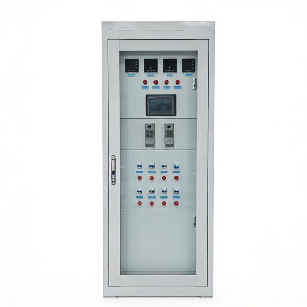
This handbook covers the code of practice in protection circuitry including standard lead and device numbers, mode of connections at terminal strips, colour codes in multicore cables, dos and donts in execution. Also principles of various protective relays and schemes including special protection. Relay systems protect high-voltage equipment and transmission lines to ensure safe, stable systems. Ensuring that. lectrical work practices. See NFPA 70E in the USA, e conduit nut provi ource termination point. * NOTE: When connecting the control side of this device (#18 wires) to power line circuits, provide curre. 1/3HP@120V. The testing and verification of relay protection devices can be divided into four groups: Type tests are needed to prove that a protection relay meets the claimed specification and follows all relevant standards. Since the basic function of a protection relay is to correctly function under abnormal. Manual intended for personnel responsible for installing, commissioning and using VIP protection 400. The handbook for protection engineers includes guidelines on protective circuitry, protective relay principles, and testing procedures for switchgear and relays. It covers standard codes, wiring practices, and norms for protecting generators, transformers, and lines, and provides detailed.
[PDF]

Use your pliers to twist the pigtail wire and the ground wire together. Snip the sharp edge at the terminal and then insert it into the wire cap. If your metal box is in use, secure a green screw in the threaded opening at the back of the metal box. In this guide, I will teach you how to pigtail ground connections in metal and electrical boxes, and how to make a perfect pigtail. Below I will provide straightforward. Pigtailing is an essential electrical wiring technique used when adding devices or when there aren't enough spaces in a junction box. 📌 What You'll Learn in. If you have a pigtail for three wires (say # 14 AWG if that makes a difference) together in a wire nut but you want to add another wire to the mix. Is the proper method to undo the wire nut and untwist them and try to straighten out all three as best as possible? (In IT there was a tool to. Before diving into the mechanics of twisting, it's crucial to understand the two primary components involved: the wire itself and the pliers you'll be using. The success and durability of your twist depend heavily on selecting the appropriate materials and tools for the job. This technique is often employed when three or more wires need to be joined, ensuring that the. A pigtail wire is a short cable used to lengthen short wires. Also, it can join several wires to become a single conductor for electrical connections. The National Electrical.
[PDF]