
The fusion method fuses the fiber cores together with less attenuation. Fusion splicing stands out as a superior technique for joining optical fibers, offering a seamless, low-loss connection that is crucial for reliable fiber optic networks. Thorlabs offers a varied selection of single mode (SM), polarization-maintaining (PM), multimode (MM), and double-clad fiber couplers, as well as 1x8 and 1x16 SM PLC splitters; 1x4, 1x8, and 1x16 PM PLC splitters; wideband multimode circulators; RGB combiners; and WDMs. Our SM and double-clad fiber. Castor's Multimode Fiber Splitters (MFS) are designed to efficiently split or combine multimode signals with minimal insertion loss. Manufactured with step-index fibers with core diameter ranging from 50 to 400 µm, they offer uniform splitting ratios across output channels. This method provides a simple, rugged, and compact method of splitting and combining optical signals. Let's explore the fundamentals of mechanical and fusion. A fiber optical coupler (splitter/combiner) route signals to their appropriate destination by splitting, combining or tapping optical signals/channels in a fiber transmission link. Employing a unique fiber fusing process, Lfiber is now able to fabricate and offer a wide variety of fiber optic. Fused couplers are ideal components to split or combine light signals between two fibers over a wide wavelength and temperature range.
[PDF]

Since the earliest days of fiber optics, multimode cables have typically been color‑coded orange, black, or gray, while single‑mode cables are marked in yellow. For example, cable jacket color typically defines the fiber type, and can differ based on mode and performance level. These colors are typically chosen by industry standards bodies. However, there are some non-standardized colors and inconsistencies that you should be aware of. However, with the introduction of metallic connectors like FC and ST—whose bodies are difficult to color‑code—colored strain relief boots. Multimode fiber (MMF) is a kind of optical fiber mostly used in communication over short distances, for example, inside a building or for the campus. Multimode fiber optic cable has a larger core, typically 50 or 62. 5 microns that enables multiple light modes to be propagated. Because of this, more. Originally developed by the Electronic Industries Alliance (EIA) and the Telecommunications Industry Association (TIA), the TIA-598-D standard (formerly EIA/TIA-598) remains the most recognized color-coding system for optical fibers worldwide. On the right, the yellow patchcord indicates singlemode fiber and the blue connector means it is a regular PC polished connector, If it were an APC connector, it would be green. Perhaps nothing is.
[PDF]
Glass fiber and plastic fiber is fragile. When individual fibers break, light transmission and uniformity are reduced. After the first few fibers break at a stress point, a chain reaction occurs, hastening t.
[PDF]

Manta HM (stands for "high magnification") is an automated microscope for inspection of single and multi-fiber patch cords, bulkhead and transceivers, including but not limited to: MT, MPO, SN-MT, MMC, LC, FC, SC, CS®, SN®, MDC, E2000™, MXC, PRIZM, QSFP, ARINC . Manta HM (stands for "high magnification") is an automated microscope for inspection of single and multi-fiber patch cords, bulkhead and transceivers, including but not limited to: MT, MPO, SN-MT, MMC, LC, FC, SC, CS®, SN®, MDC, E2000™, MXC, PRIZM, QSFP, ARINC . Image shown is a representation only. Exact specifications should be obtained from the product data sheet. Order today, ships today. F3-SDLCLC-HM – Cable Fiber Optic LC/UPC Duplex To LC/UPC Duplex 9/125 1. 64' (500mm) from CompuCablePlusUSA. Pricing and Availability on millions of electronic. Buy now, ships today. that performs on-site drawing of copper. When drawing copper, PCA starts with 13 AWG solid copper conductor on custom built deploying devices, called Stems. The copper is pulled into drawing. CESS, 3 HOLE OT P NG S, 3 HO.
[PDF]

This practical file details experiments conducted in Optical Fiber Communication, covering modulation techniques, system components, and performance analysis. An optical fiber is a glass or plastic fiber designed to guide light along its length, widely used in fiber-optic communication, which permits transmission over longer distances and at higher data rates than other forms of communications. Fiber-optic communication is a method of transmitting. Availability of plastic optical fiber (POF) The plastic optical fiber used in some of these experiments is available for science distributors. It is a 1000micron (1mm) POF available from several suppliers. FOA has samples available at no cost for teachers at schools in the US. Key experiments include amplitude modulation, frequency modulation, and pulse width modulation, aimed at understanding fiber optic systems. This document summarizes 10 experiments on optical fiber communication: 1. Studying a 650mm fiber optic analog link and the relationship between input and received signals. Optical fiber communication Laboratory Optical fiber communication Laboratory List of Experiments: 1. To set up a analog optical fiber link 2. To measure the characteristics of LED and LASER 5. Tech curriculum designed to provide a comprehensive understanding of optical fiber communication systems. This lab offers an immersive, web-based simulator that enables you to explore and experiment with key concepts in optical.
[PDF]
6Wresearch actively monitors the Palau Fiber Optics Cable Market and publishes its comprehensive annual report, highlighting emerging trends, growth drivers, revenue analysis, and forecast outlook. Our insights help. Est. Freight Cost? date (-30 days from arrival). Click here to find out more. Buyers typically pay for fiber optic cable by length, fiber type, and installation complexity. Main cost drivers include cable grade (indoor vs outdoor, armoured), distance, and labor for trenching, splicing, and termination. This guide presents ranges in USD and practical price estimates to help. CRU provides comprehensive, accurate and up-to-date price assessments and research reports for bare optical fibre across various key regional markets, combined with insights into the factors and events affecting markets. How does 6W market outlook report help businesses in making decisions? 6W monitors the market across 60+ countries Globally, publishing an annual market outlook report that analyses trends, key drivers, Size, Volume, Revenue, opportunities, and market segments.
[PDF]

Arduino-Powered Data Transmission with Fiber Optics Welcome to our video tutorial on optical communication with Arduino, designed to be easy t. more. They consist of a transmitter on one end of a fiber and a receiver on the other end. Most systems use a "transceiver" which includes both transmission and. I'm going to use HFBR 1414 fiber optic transmitter module which is manufactured by Broadcom. It is a low-cost high-power transmitter that is designed for use in industrial power generation, power distribution, medical transportation and gaming applications. Internally, the optical fiber consists of a highly reflective central core, which acts like a light guide. Media converters are special fiber optic transceivers used to convert from one type of cable (the media) to another, typically from copper cables to fiber optics, although some media converters will convert from one fiber type to another, e. multimode to singlemode. The FOA Guide has a page about. A fiber optic transceiver (also called an optical transceiver) is a compact module that both transmits and receives data signals through optical fibers. It serves a dual purpose — transmitting electrical signals as light pulses and receiving light pulses to convert them back into electrical form.
[PDF]

The number of optical cores in an optical fiber is the total number of equipment interfaces multiplied by 2, plus 10% to 20% of the spare quantity, and if the communication mode of the equipment has serial communication and equipment multiplexing, you can reduce the number of cores. A fiber optic cable typically has multiple cores, depending on its design and purpose. The most common type of fiber optic cable used in telecommunications is single-mode fiber, which usually has a single core. This post will guide you through understanding fiber optic cores and selecting the perfect cable for your needs. Understanding Fiber Cores: Core: The central glass fiber that transmits light signals. Single-mode: A. The total number of cores for a 1pc fiber patch cable is calculated as the number of branches multiplied by the number of cores per branch (if there are no branches, the number of branches = 1). The number of. This guide walks you through the simple decision steps engineers use, the common strand counts on the market, and clear rules-of-thumb for different project types so you choose a cable that fits both today's needs and tomorrow's growth. Begin by listing what the network must support now and in five. Fiber optic cables are used to transmit data and audio signals using light. They come in different types, each designed for specific applications and distances.
[PDF]

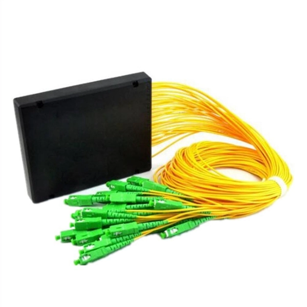
The box is typically composed of several parts, including the enclosure, the splitter module, and the connectors. An optical cable split fiber box is a device used in fiber optic communication networks to split the signal from one input into multiple outputs, allowing multiple devices to be connected to a single fiber optic cable. This provides users with a dependable and high-speed network service and little to no wait times. There is no need for an FDB if there is no. In modern FTTH (Fiber to the Home) and optical communication networks, three types of fiber distribution products are widely used: Splitter Distribution Box, ODF (Optical Distribution Frame), and Fiber Terminal Box. Although they all belong to the optical distribution and management system, their. A fiber optic splitter is a passive optical component that divides a single incoming optical signal into two or more outgoing signals, or combines multiple incoming signals into one. It can divide the input optical signal into multiple output optical signals to meet the fiber optic access needs of multiple terminal devices. This type of device plays an important role in passive. In this kind of fiber cabinet, the backbone fiber optic cable usually does not connect to optical splitters. However, in some metropolitan area, the backbone fiber cable will.
[PDF]

Fusion splicing is the process of fusing or welding two fibers together usually by an electric arc. Fusion splicing is the most widely used method of splicing as it provides for the lowest loss and least reflectance, as well as providing the strongest and most reliable joint between. This guide reveals the secrets to fusion splicing with little fluff—just proven, straightforward techniques refined from years of work in the field. The goal is to fuse the two fibers together in such a way that light passing through the fibers is not scattered or reflected back by the splice, and so that the splice and the region surrounding it are almost as strong as the. A fusion splicer is a specialized tool used in fiber optic networks to join two fiber optic cables together permanently. This process creates a strong and reliable connection that can withstand. Splicing fiber optic cable is an extremely important phase for making dependable, high-speed communication infrastructures. Fusion splicing stands out as a superior technique for joining optical fibers, offering a seamless, low-loss connection that is crucial for reliable fiber optic networks. Let's explore the fundamentals of mechanical and fusion.
[PDF]

Receiver sensitivity is the lowest optical power level at which an optical receiver can successfully decode data with acceptable bit error rates (BER). It's a core parameter in optical transceiver specifications, indicating the module's capability to detect weak incoming signals. The standards body governing the application sets this specified BER. For example, SONET specifies that the BER must be 10 -10 or better. What Is BER? The bit error rate (BER) measures the data transmission precision within. Receiver sensitivity stands as a critical parameter impacting an optical transceiver's functionality. It denotes a module's capability to function in challenging environments and aids network operators in determining the system's maximum reach or link margin. Lower receiver. Among a group of optical receivers, a receiver is said to be more sensitive if it achieves the same performance with less optical power incident on it. The performance criterion for digital receivers is governed by the bit-error rate (BER), defined as the probability of incorrect identification of.
[PDF]

An SC/APC fiber optic adapter is a passive mechanical interface used to join two SC connectors that have angled physical contact (APC) ferrules, typically polished at 8°. Fiber couplers belong to the basic components of many fiber-optic setups. Note that the term fiber coupler is used with two different meanings: It can be an optical fiber device with one or more input fibers and one or more output fibers. It covers a wide range of fiber optic devices such as optical splitters, optical combiners, and optical couplers. A fiber optic coupler is a device that can distribute the optical signal. This small, inexpensive component is critical for aligning and mating two SC/APC connectors while preserving low insertion loss and ultra‑high return loss performance. Its core function is to distribute (split) or combine (combine) optical power while maintaining the spectral composition of the signal. The device allows the transmission of light waves through multiple paths. It functions by dividing a single incoming light path into multiple outgoing paths, or by combining light from several input paths into a single output fiber. This capability is fundamental.
[PDF]

An armored optical cable is a type of fiber optic cable reinforced with a protective layer—usually corrugated steel tape (STA) or steel wires (SWA) —to shield the internal fibers from external threats such as crushing, rodent bites, moisture, and harsh installation conditions. With a durable protective layer, they are ideal for harsh or high-traffic environments. This article explains what armored fiber cables are, their key. Every optical fiber cable project faces the same critical question: should you choose an armored cable or a non-armored one? At first glance, the choice may look simple. Armored cables appear stronger, non-armored cables are cheaper. But the real decision is not that easy. The wrong choice can: Or. With the increasing demands on high-performance connectivity, for many buyers, choices boil down to two quite popular options: the outdoor armored fiber optic cable and the standard optical fiber cable. In this blog post, we'll explore the advantages and disadvantages of. Armored and non-armored fiber optic cables are engineered for different levels of mechanical protection, environmental resistance, and installation conditions. You select between them based on route exposure, rodent risks, burial requirements, tension loads, and overall ODN architecture. An under-armored cable in a harsh environment leads to fiber damage, network outages, and costly repairs. Over-specifying armored cable where standard cable suffices.
[PDF]

If you are ever in need of checking your ONT, this video will show you how to do so and what it is you are looking for. Always remember to securely close the box afterwards to prevent any damage to the facilities inside. more. A fiber termination box is the standard instrument used in fiber optic networks to connect, secure, and protect optical fibers at the terminating point. It functions as a junction between the incoming fiber cable and the outgoing customer-side fiber cable, where one fiber can be spliced, patched. Open the Fiber optic terminal box. Check and prepare installation tools and accessories. Prepare the cable according to the design. An ONT, or Optical Network Terminal, is the box where your fiber internet connection enters your home to power your fiber network. Your ONT is typically located in your garage, basement or outside your home within a few feet of your home's power box. It serves as a termination point for optical fibers, providing a secure and organized space for connecting and managing fiber optic cables. A fiber pigtail is a specific hardware connection used for cable termination. Proper installation and maintenance of FTBs are essential to ensure the reliability and performance of the network infrastructure.
[PDF]

Fiber optic pigtails are short, single, or multi-strand pieces of optical fiber cables with a connector on one end and exposed fiber on the other end. They are typically used to terminate fiber optic cables and connect them to patch panels, equipment, or other termination points. Fiber pigtails are simple in appearance, yet essential in function. Despite this ubiquity, they remain a source of confusion for procurement teams and junior installers alike—especially when it comes to connector type selection, polish type, and the tradeoffs between mechanical. Fiber Optic Pigtails, also known as pigtailed fibers, consist of an optical fiber connector and a section of optical cable. Characterized by having an optical fiber connector on one end and a bare fiber end on the other, they are primarily used to connect optical transceivers or other optical. A Fiber Optic Pigtail Complete Guide: As per types, connectors, and applications. In such contemporary fiber optic communication systems, low-loss, and connectivities, which have reliability, are crucial for not only maintaining high-speed but also high-quality data transmission. It is usually suitable for field termination using a mechanical or fusion splicer. Compared with quick termination or epoxy and polish connections placed on the field.
[PDF]
