Select the correct wavelength and set your reference. You measure optical power in dBm or insertion loss in dB. Consistent procedures ensure accuracy. Measure total signal loss from fiber, connectors, or splices. Optical fiber attenuation is the attenuation per unit length of optical fiber, and the unit is dB/km. When connecting two optical fibers, there will be loss inside any connector or joint. Consistent measurement techniques. While optical power meters are the primary power measurement instrument, optical loss test sets (OLTSs) and optical time domain reflectometers (OTDRs) also measure power in testing loss. TIA standard test FOTP-95 covers the measurement of optical power. Optical power is based on the heating power. Light Source: The CMA5 Series Light Sources provide an economical and stable laser source for use in point-to-point attenuation measurement. They feature a rugged design, built to withstand the difficult testing environment of fiber optic cable installation and maintenance. The CMA5 Light Sources. When talking about optical measurements, wavelength basically means how far a wave pattern repeats itself, usually measured in nanometers (nm). Commonly, a power meter on its own is used to measure absolute.
[PDF]

The core measurement procedure follows five steps: Turn on the meter and let it warm up. Most meters need a brief stabilization period before readings are reliable. Check your model's manual, but a minute or two is typical. Set the wavelength to match your light source. Fiber loss is the difference between the power when light is coupled from the transmitting end to the fiber and the power when the light reaches the receiving end. Generally speaking, when measuring the. An optical power meter measures the strength of light traveling through a fiber optic cable, giving you a reading in dBm (decibels relative to one milliwatt). The basic process is straightforward: turn the meter on, set it to the correct wavelength, clean your connectors, plug in, and read the. A power meter and light source are essential test tools that work in tandem to measure fiber optic cable loss and evaluate the quality of optical links. They provide the data necessary to quantify signal loss and pinpoint issues that could impact network performance. Here's how they work: A power. You measure optical power in dBm or insertion loss in dB. Verify light travels from transmitter to receiver. We'll give you the basic information you need and provide some printable references.
[PDF]
In 1880, and his assistant created a very early precursor to fiber-optic communications, the, at Bell's newly established in. Bell considered it his most important invention. The device allowed for the of sound on a beam of light. On June 3, 1880, Bell conducted the world's first wireless transmission between two buildings, some 213 meters apart. Due to its use of an atmospher.
[PDF]

To use a power meter for fiber optic testing, always clean connectors first with lint-free wipes or click-to-clean tools. Select the correct wavelength and set your reference. You measure optical power in dBm or insertion loss in dB. Consistent procedures ensure accuracy. Verify light travels from. The most basic fiber optic measurement is optical power from the end of a fiber. This measurement is the basis for loss measurements as well as the power from a source or presented at a receiver. Typically both transmitters and receivers have receptacles for fiber optic connectors, so measuring the. An optical power meter measures the strength of light traveling through a fiber optic cable, giving you a reading in dBm (decibels relative to one milliwatt). This article will guide you through the methods, instruments, and key considerations for measuring fiber. Fiber optic cabling is the high-performance core of today's datacom networks. As network speeds and bandwidth demands increase, fiber performance requirements have become more stringent. Fiber testing is more important than ever. An OPM uses a photodiode to generate an electrical current proportional to optical power.
[PDF]

This standard covers the construction, mechanical, electrical, and optical performance, installation guidelines, acceptance criteria, test requirements, environmental considerations, and accessories for a nonmetallic, all-dielectric self-supporting (ADSS) fiber optic cable. An All-Dielectric Self-Supporting (ADSS) cable operates without metallic messengers, relying entirely on its aramid yarn strength members. For a typical 12-fiber ADSS cable with a 8. AFL-ADSS® (All-Dielectric Self-Supporting) cable is ideal for installation in distribution as well as transmission environments. This guide provides general recommendations for the selection of methods, equipment, and tools for the stringing of ADSS (All Dielectric Self-upporting) fiber optic cables including short and Long Span ADSS cables. The installation methods for ADSS cables are essentially the same as those used for. This Installation Manual is a recommendatory installation document provided by HANGZHOU ZION COMMUNICATION CO. The installation manual is established based on the newest issued international standards such as lEEE Std 1222: 2004, "lEEE standard for all-dielectric. Round aramid reinforced ADSS cable for intermediate and long spans, 4 – 96 fibres. VDE: A- DF 2Y (ZN) 2Y This specification covers a family of optical cables with 4 - 96 fibres for intermediate and long spans.
[PDF]

The operation and skills of fiber optic fusion splicing technology can be mainly divided into five steps: fiber stripping, fiber cutting, fiber melting, fiber sleeve, and fiber winding. Two types of splices are used in fiber optic cabling one is Mechanical the other is Fusion. And tools used for fiber fusion: fusion splicer; fiber cleaver; cable stripper; fiber optic stripper; alcohol;. These specialized devices are engineered to manipulate, terminate, join, and verify light-carrying strands without introducing microscopic fractures or contamination. At Weunion, we categorize these essential instruments into four primary operational phases: Preparation: Removing protective layers. Various techniques can remove the coating: Regardless of the method used to strip the coating, it is important to use the correct tools and techniques to prevent damage to the bare glass. Ensuring the fiber. What is Fiber Optic Splicing and Why is it Needed? – #1. Use and Maintain Your Cleaver Correctly – #3. Set Your Fusion Parameters in a Systematic Way What is Fiber Optic Splicing and Why is it Needed? First, let us understand the meaning of the term. Fusion splicing joins two optical fibres end-to-end using heat, creating a seamless connection for minimal signal loss. owever, proper cable preparation is essential before firing up your fusion splicer. A poorly prepared fibre can lead to weak splices, high attenuation, or complete failure.
[PDF]
Explore 20 top manufacturers and suppliers of Optical Time-Domain Reflectometers in our comprehensive photonics buyers' guide. Importer and distributor of photonics components and subsystems for use in instrumentation. Optical time-domain reflectometers (OTDRs) are measurement instruments that inject optical pulses into a fiber and measure the returning light scattered by Rayleigh scattering or reflected by Fresnel reflections. Products include photomultiplier tubes, solid-state photodetectors, IR. Time-Domain Reflectometers (TDR) and Optical Time-Domain Reflectometers (OTDR) are essential tools used in telecommunications, fiber optics, and cable testing industries for analyzing the integrity of cables and pinpointing faults. Various time-domain reflectometers are available, intended for different uses and requirements. These are some of the reflections using a comparative TDR. Our catalog includes 106,303 manufacturers, 20,788 distributors and 94,584 service providers.
[PDF]

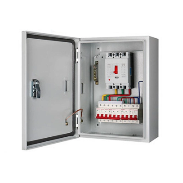
In this video, we'll show you how to connect an energy meter to a distribution board (DB) safely and efficiently. energy meter connection with distribution box How to Connect an Energy Meter to Your Distribution Box Easily Steps to Properly Connect Your Energy Meter to a Distribution Box. It plays a vital role in ensuring the safe and efficient distribution of electricity throughout the premises. What is the wire from the meter to the breaker box? Also. Always begin with disconnecting the main supply before accessing any enclosure containing distribution components. This prevents arc faults and ensures safety when modifying or inspecting current paths. This “meter to panel” wiring establishes the pathway for all incoming electrical power from the grid to the home. Its primary function is to safely and reliably. Distribution Board aslo know as “Panel Board”, “Switch & Fuse Board” or “Consumer Unit” is a box installed in the building containing on protective devices, such as circuit breaker, fuses, isolator, switches, RCDs and MCBs etc. The electric main supply (230V AC & 120V AC in US) is connected through. Changed Texas's reference diagram for the 3 wire network 120/208 Volt single phase self-contained Revised Figures 13, 14, 14b. Limited the meter location from pad mount transformer for PSO. Removed unistrut being listed as an alternative means for mounting the meter box. APCo and TX do not allow.
[PDF]

Product Features: Square protective box, suitable for skin cable and leather cable tight protection 6cm in length of skin heat shrink tube welding protection. A close connection between the leather cable and pigtail. Looking for specific info?. *In the era of high bandwidth, reliable fiber optic power equipment is particularly important. This handheld photometer can help check cable performance, calculate relative power loss, locate faults, and troubleshoot. *Measure the length of network cables, coaxial cables, and telephone cables. Able. Usually ships within 3 to 4 weeks Click here for details of availability. Able to test open, short, cross-connect, See more product details TABKER 4000667180167 3 x 2 x 1. Check each product page for other buying options. Price and other details may vary based on product size and color. Need help?. power across any given fiber. This document will serve as an overview of the major features and functions of the device and will ofer tips for trouble shooting com on issues in optical networks. If you are looking for a low cost device capable of saving and reporting take a look at the RP460 or. ments to the instrument's performance and functionality. The figures given in this manual ion of this manual to ensure the accuracy of its contents. However, should you have any questions or fi gistered users with a variety of information and services. Please allow us to serve you best by.
[PDF]

Continuous-wave operation (cw operation): The laser is continuously pumped and emits light continuously, either on a single resonator mode (→ single-frequency operation) or on multiple modes (see also: single-mode operation). How do optical. EML stands for Externally Modulated Laser (corrected from "External Modulated Laser"). Its basic principle is to supply a constant current to the laser diode, ensuring the LD emits continuous, stable light. An external electro-absorption modulator (EAM) then adjusts light transmittance to generate. A wavelength swept light source emits laser light with a continuously sweeping wavelength. It is suitable for shape measurement and displacement measurement utilizing OFDR (Optical Frequency Domain Reflectometry), an optical sensing method using the coherence of laser light. The transmitting interface inputs electrical signals of a certain bit rate, which are then processed by internal driver chips. Subsequently, the driver semiconductor laser. Industry pundits have recently speculated that demand for 100G/400G switches may take off in 2019, prompting optical transceiver module vendors to sample data center switches with high data transmission rates earlier than expected. As data center operators accelerate upgrades in preparation for 5G.
[PDF]

A fiber-optic splitter, also known as a beam splitter, is based on a quartz substrate of an integrated waveguide optical power distribution device, similar to a coaxial cable transmission system. The optical network system uses an optical signal coupled to the branch distribution. The fiber optic. In the backbone of modern Fiber-to-the-Home (FTTH) networks, optical splitters serve as the unsung heroes that enable cost-efficient connectivity for millions of subscribers. By dividing a single optical signal from a central Optical Line Terminal (OLT) into multiple outputs for Optical Network. Optical splitter, also called optical beam splitter, is an integrated waveguide optical power distribution device that can split an input optical signal into two or more output optical signals, and the optical input power is evenly distributed on all output ports. For example, an optical splitter. The answer lies in a small device. We call it an Optical Splitter. This device is the heart of Passive Optical Networks (PON). It allows service providers to save money. It helps them distribute bandwidth efficiently. In this article, we explain the definition, working principles, types, and. An optical splitter is a device that divides light transmission in a network into multiple output ends. It plays a crucial role in facilitating network interconnections.
[PDF]

These networks rely on optical fibers, which are thin strands of glass or plastic that carry light signals. The ONU serves as the termination point of a fiber-optic network, converting the optical signals back into electrical signals for distribution to end-user devices. A GEPON system usually consists of an OLT (Optical Line Terminal) at the service provider's central office and multiple ONU (Optical Network Units) or ONT (Optical Network Terminals) close to the end user as optical splitters. In addition, the transmission between OLT and ONU/ONT adopts an optical. In the realm of Fiber-to-the-Home (FTTH) and other FTTx architectures, the Optical Network Unit (ONU) is a critical piece of customer-premises equipment (CPE). The primary function of an. ONU stands for Optical Network Unit. Think of it as. ONU (Optical Network Unit) plays a crucial role in modern telecommunications, enabling seamless connectivity and high-speed data transmission across fiber optic networks. As global demand for Fiber-to-the-Home (FTTH) expands, ONUs have become essential for delivering reliable broadband to homes. As an essential node in Passive Optical Networks (PON), the ONU not only handles the conversion between optical and electrical signals but also supports various services such as data, IPTV, and voice. This article will provide a detailed explanation of the working principles of ONUs and their.
[PDF]
TendersOnTime, the best online tenders portal, provides latest Gabon Cable tenders, RFP, Bids and eprocurement notices from various states and counties in Gabon. TendersOnTime, the most comprehensive database for Government Tenders and International Tenders; collects information on Cable from. This tender with title Supply and installation of fiber optic cables at the headquarters of the FAO Sub-regional Office for Central Africa in Libreville/Gabon. - 5563580 has been published on Bidding Source portal dated 07 Sep 2025 for the country of Gabon. It has been categorized on Optical-fibre. La Fourniture Et Pose De Câbles En Fibre Optique Au Siège Du Bureau Sous-Régional De La Fao Pour L'Afrique Centrale À Libreville/Gabon. FAO Gabon has. Most trusted source for Tendering Opportunities and Business Intelligence since 2002 Get access to latest Gabon cables tenders and government contracts. The project location is Gabon and the tender is closing on 15 Sep 2025. The tender notice.
[PDF]
PAM4 is a modulation scheme that combines two bits into a single symbol with four amplitude levels as shown in Fig. This effectively doubles a network's data rate, enabling 400G/800G short-haul transmission. NRZ, or Non-Return-to-Zero signaling, represents binary information using two distinct signal levels: This creates relatively wide signal separation between logical states. As a result, NRZ systems historically provided: This operational tolerance helped earlier architectures remain relatively. PAM4 is a branch of the pulse amplitude modulation (PAM) technology, which is a mainstream signal transmission technology following non-return-to-zero (NRZ). Playing a key role in multi-order modulation, PAM is widely used in high-speed signal interconnection. Figure 1-1 shows the typical waveform. A key new modulation scheme, PAM4, was introduced around 2017 and enabled the big jump from 100G to 400G. When it comes to enabling 400G and higher Ethernet speeds, a four-level pulse amplitude modulation or PAM4 multilevel signaling is needed as opposed to the non-return-to-zero (NRZ) modulation.
[PDF]
Pricing (USD) Filter the results in the table by unit price based on your quantity. Fairview Microwave Coaxial Cables are available at Mouser Electronics. Price when purchased online Shop for Optical Audio Cables in TV Accessories. Buy products such as VANAUX Optical Audio Cable, TOSLINK S/PDIF Digital Optic Cord, Fiber Audio Cable, Gold-Plated, Nylon Braided for Home Theater, Sound Bar, TV, PS4, Xbox, PlayStation (10ft/3m) at Walmart and save. Check each product page for other buying options. Need help? Find reliable Toslink fiber optic cables for your home audio setup. Available in multiple lengths with corrosion-resistant connectors. Thorlabs' Microwave Cables and Adapter Cables are flexible, high-performance, coaxial cable assemblies designed for use out to 50 GHz, depending on connector type (see Figure 1. The design gives these cables flexibility while maintaining optimal performance. Mouser offers inventory, pricing, & datasheets for Fairview Microwave Coaxial Cables. Explore high-quality optic cables for digital audio, including Toslink, mini Toslink, and gold-plated ferrules. Choose from various lengths, such as 1. These cables are used for many long-distance telecommunications systems, but they can also create high-speed data connections within your home with devices like a or.
[PDF]