Simple 3-phase distribution board wiring diagram for home use, showing safe connection of power supply, breakers, neutral, and earth for residential electrical systems. Hey, in this article we are going to see the Three (3) Phase Distribution Board Wiring Diagram and Connection Procedure. The three-phase distribution board is used to distribute power to the three-phase loads and circuits such as three-phase motors, three-phase machinery, three-phase to. A distribution board, also known as a DB box, is like the central hub of an electrical system. It contains multiple circuit breakers and connects various electrical circuits to ensure the safe flow of electricity throughout the building. Unlike single-phase systems, where power is distributed using. When it comes to understanding the basics of electricity and wiring, a wiring diagram of a three phase distribution board is indispensable. This diagram shows how electricity is distributed in a home or building and helps you identify which connections should be made when constructing, modifying or. Welcome to our channel! In this video, we'll walk you through the process of wiring a home distribution box with a detailed connection diagram. Whether you're an electrician or a DIY enthusiast, this guide will help you understand the basics of home electrical distribution. These setups typically provide 240V for most applications, but it's crucial to follow the proper configuration to prevent hazards.
[PDF]

This publication shows how to wire and install the 4010-9825 24V Distribution Block into a 4010 Fire Alarm Control Panel (FACP). Refer to the 842-058 Field Wiring Diagram for additional wiring information. 1 Transformer connection: Two red wires connect to AC 220V input port, while two yellow wires connect to AC input port of main board (had connected by the factory. 2 DC12V battery connection: Red wire on the circuit main board connects to the positive pole of acid-lead battery while black. Notify the carrier and call Telect's Customer Service Department at 1-800-551-4567. Keep the container until you have checked equipment operation. Use the original, undamaged container if you are instructed to return. Learn how to wire a distribution box step by step! This video shows real on-site footage of electrical installation, demonstrating safe and standardized wiring methods used by professionals. Such a system, however, does not assure. Material preparation: Prepare the required circuit breakers, wires, wiring ties and other materials, and ensure that they meet the design drawings and installation requirements. Location determination: Determine the installation position of the circuit breaker according to the position of the.
[PDF]
Check for proper IP/NEMA ratings and material quality. Ensure safe placement: install in dry, accessible areas with good ventilation and at appropriate height (typically ~1. Practice good wiring: secure grounding, neat cable management, proper insulation, and correct wire gauge. In this video, we'll walk you through the process of wiring a home distribution box with a detailed connection diagram. Whether you're an electrician or a DIY enthusiast, this guide will help you understand the basics of home electrical distribution. more Welcome to our channel! In this video. However, the key to a safe and reliable system lies in proper installation. If it's done poorly, you risk short circuits, fire hazards, or system failure. Done right, it ensures safety, compliance, and long-lasting performance. In this guide, we'll break down everything you need to know to install. Distribution board is a safe system designed for house or building that included protective devices, isolator switches, circuit breaker and fuses to safely connect the cables and wires to the sub circuits and final sub circuits including their associated Live (Phase) Neutral and Earth conductors. Learn how to wire a single-phase household distribution box in just 60 seconds! In this quick tutorial, we'll cover the essential components and wiring steps for a safe and efficient distribution setup in residential areas.
[PDF]
The 11-in-1 Screwdriver includes the 8 bits and 3 nut drivers most requested by professionals. The bit prevents bit wear from hardened screws and extends bit life when fastening specialty screws found in elec.
[PDF]

Ensure safe placement: install in dry, accessible areas with good ventilation and at appropriate height (typically ~1. Practice good wiring: secure grounding, neat cable management, proper insulation, and correct wire gauge and breaker size. The term “four wires” refers to three live wires and one neutral wire, designated as A|B|C|N|, with N representing the ground wire. The three live wires should be connected to the upper entry of the main switch in the explosion-proof distribution box, and the neutral wire should be directly. Learn how to wire a distribution box step by step! This video shows real on-site footage of electrical installation, demonstrating safe and standardized wiring methods used by professionals. This ensures compliance with NEC and simplifies troubleshooting. Include protection devices like breakers, fuses, and. Prevention of Electrical Hazards: Proper wiring ensures that electrical currents flow smoothly and safely through the circuits, minimizing the risk of electrocution and electrical accidents. Faulty wiring can result in electric shocks and even be life-threatening. Efficient Power Distribution: The. ormal operation due to poor manufacture quality. A paid repair will be provided if the warranty period expires. For any damage due to one of the following situations, a paid repair duct, please dispose the pro ype, a “R” is added after the Specification. For single row 20, and circuit 24, fter.
[PDF]

Whether you're an electrician or a DIY enthusiast, this tutorial will help you understand the fundamentals of wiring a distribution box for a residential setup. The diagram of the distribution board's wiring shows exactly how each circuit is wired and connected. What is Distribution Board? Distribution board. A distribution box is the heart of any electrical system. It takes the incoming power and safely distributes it to different circuits throughout your building. Whether in a home or an industrial facility, this box keeps your electrical setup organized, functional, and efficient. However, the key to. In this guide, we will break down the key elements involved in connecting the main power supply to your home, providing a clear path for a successful setup. We will focus on the critical parts of the system, from basic components to step-by-step assembly procedures. It serves as a central hub for distributing electricity throughout a building, ensuring that power is delivered safely and efficiently to all the required locations.
[PDF]

This guide shows you how to organize circuit breaker wiring properly. You will learn to build a safe, efficient, and professional electrical system today. Circuit breaker wiring configurations involve organizing main switches, busbars, and branch breakers within a distribution box. Messy distribution boxes are dangerous and very hard to fix. It takes the incoming power and safely distributes it to different circuits throughout your building. Whether in a home or an industrial facility, this box keeps your electrical setup organized, functional, and efficient. The distinction between 1P and 2P circuit breakers plays a pivotal role in determining the appropriate protection level for various circuits. Learn how to wire a distribution box step by step! This video shows real on-site footage of electrical installation, demonstrating safe and standardized wiring methods used by professionals. It serves as a central hub for distributing electricity throughout a building, ensuring that power is delivered safely and efficiently to all the required locations. At the heart of a breaker box is the main breaker, which controls the flow of electricity from the utility into the building. From the main breaker, power is sent to individual circuit breakers, each of.
[PDF]

This installation note provides the installation instructions for the Cisco small form-factor pluggable (SFP) and SFP+ transceiver modules. This document is intended to serve as a guide for architecting and deploying fiber optic networks in a customer environment. These transceiver modules are hot-swappable input/output (I/O) devices that plug into 100BASE, 1000BASE and 10GBASE ports (for SFP+), which connect the module. This manual provides safety and installation instructions for the 9490-OS Fiber Optic Passive Splitters. All units use type LC connectors and vary only in the splitting fan-out, and as single or dual-channel capability as listed below. Optical fibers require special care during installation to ensure reliable operation. Installation guidelines regarding minimum bend. Listings and approvals under Time Recorder Co. are the property of Tyco Fire Protection Products. Description Multiple Signal Fiber Optic Modems combine multiple system communications signals and convert them to fiber optic communications for transmission. This guide will focus on the 1x9 dual SC optical transceiver products. Pin Assignment & Description TD+, TD: DC coupled LVPECL inputs for the transmitter.
[PDF]

In the following tutorial, we will show how to wire 120V single-phase and 240V split-phase circuit breakers and loads inside a residential main panel. The figure below shows a typical breaker panel used for 120V and 240V circuits. Messy distribution boxes are dangerous and very hard to fix. You will learn to build a safe, efficient, and professional electrical system today. Circuit breaker wiring configurations involve organizing main switches, busbars. A breaker box, also known as a circuit breaker panel, is an essential component of any electrical system. It is responsible for distributing electricity throughout a building, ensuring that each circuit receives the proper amount of power. To understand how a breaker box works, it is helpful to. Each circuit is protected by a circuit breaker, a safety device that automatically shuts off power if it detects an overload or a fault. If you're looking to replace an old fuse box replacement or upgrade your home's power capacity, you'll be dealing with the load center or service panel. The distinction between 1P and 2P circuit breakers plays a pivotal role in determining the appropriate protection level for various circuits. When installing or troubleshooting a power distribution system, understanding how to correctly connect the main electrical supply to the control panel is crucial.
[PDF]
Welcome to our channel! In this video, we'll walk you through the process of wiring a home distribution box with a detailed connection diagram. It serves as a central hub for distributing electricity throughout a building, ensuring that power is delivered safely and efficiently to all the required locations. And all the switching and protective devices are installed in the. Distribution Board or DB is an electricity supply system or a common enclosure that distributes the electrical power feed into subcircuits. It includes isolator, RCCB (Residual current circuit breaker) or RCD (Residual-current device) devices, protective fuses or MCB's (Miniature Circuit Breaker). That's why having a clear, detailed diagram of your home's distribution board wiring is essential. A distribution board (also known as a service panel or breaker box) is a centralized collection of circuit breakers, fuses, and/or relays used to control and protect the wiring in a home.
[PDF]
In fiber optic circuit technology an optical fiber link is used for transferring digital or analogue data in the form light frequency through a cable which has a highly reflective central core. Internally, the optical fiber.
[PDF]

In this guide, you will learn how to interpret network diagrams like a pro, from symbols and scope to segmentation, dependencies, troubleshooting, and security clues. A rack elevation diagram is a visual representation of the equipment and components contained within a rack in a data center or server room. It provides a clear overview of the physical layout of the rack, including the placement and positioning of servers, switches, storage devices, and other. Learn how to read and interpret network diagrams effectively to troubleshoot, validate security, and plan network changes with confidence. Have you ever opened a network diagram and felt like you were staring at a subway map with no station names? That is a common problem, even for experienced IT. Network cabinet cabling describes the structured connection and arrangement of all IT components in a server rack. The aim is a secure, maintainable and scalable operation of the network environment. The amount. A standard operating procedure, or SOP, is a set of step-by-step instructions compiled by an organization to help workers carry out complex routine operations. Work instructions should be very detailed on "how" to accomplish a specific job, task or assignment. It helps teams understand network architecture, data flow, and dependencies, making it easier to design infrastructure, troubleshoot issues, and plan.
[PDF]
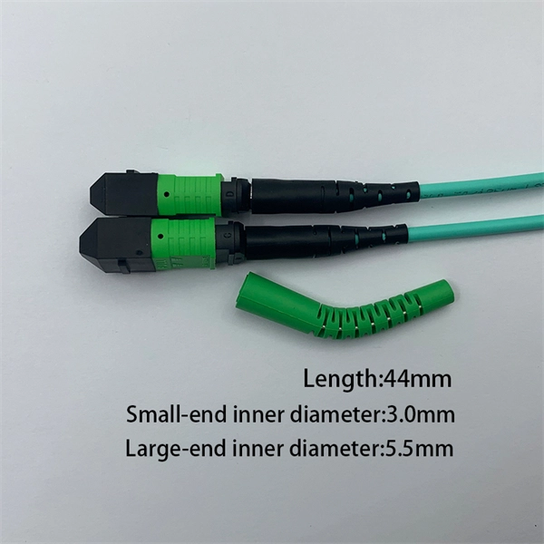
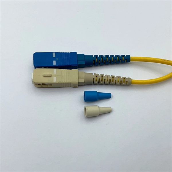
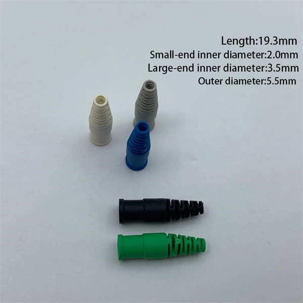
Figure 1 is a diagram of the basic construction of both loose-tube and tight-buffer fiber optic cable. An optical fiber cable is a complex structure designed to protect fragile glass fibers that transmit digital data using light signals. This advanced cabling solution allows fast, secure data transfer and telecom over long distances. Understanding the components within a fiber optic cable enables. A fiber optic cable consists of five basic components: the core, the cladding, the coating, the strengthening fibers, and the cable jacket. When searching for a fiber optic cable, we need to pay attention not only to the connectors, such as SC to ST fiber cable, LC to SC fiber patch cable, or SC to. Optical fibers are circular dielectric wave-guides used to contain and transmit light over short or long distances. They consist of three elements as shown in Figure 1: a central core, cladding and a protective coating. Understanding its internal structure is essential to appreciate how it functions efficiently in various applications, from telecommunications to medical devices. The core is the. 3,260 optical fiber structure illustrations, drawings, stickers and clip-art are available royalty-free for download. Multimode all-media self-supporting fiber optic cable structure isolated on white. More specifically, we can say that it is a waveguide that has the ability.
[PDF]

A wiring diagram for a photocell and timeclock controller provides a step-by-step guide for installing and connecting all the components in a light system. It shows exactly how each component fits into the overall scheme of things, as well as what wires to use and which connections to. Intelligent Lighting Controls' wiring diagrams show detailed schematics of our solutions. A lighting control module is the “control center” for your lighting system. It acts as a bridge between your physical lighting fixtures and the smart systems that manage them. Instead of relying solely on traditional wall switches, you can control your lights via remotes, mobile or web apps. This guide will discuss the steps needed to integrate with URC Total Control. Commission CSI Controllers Step 2. Locate/Download latest TCM files/Module Step 3. Network Setup Step 6. Supports DALI V2 compatible switches and sensors, works out of the box. Simple and easy setup. ControlByWeb® IoT controllers are a great fit for lighting control in edge applications. Understanding the components that make up a modern lighting system, and how they relate to one another is key to ensuring the best performance and.
[PDF]
Proper planning for installing cable tray includes calculations based on loading, support systems, cable/wire fill and spacing, conductor types, securing of the cables and wire, and proper grounding and bonding are all important aspects of cable tray installation. How about organizing your wiring with a cable tray system? Smart move. Whether you're building a commercial setup or upgrading an industrial plant, proper cable tray installation ensures neat wiring, safe access, and easy maintenance. This guide covers the critical steps, from selecting the right electrical cable tray and performing accurate cable fill. Cable tray installation implies the construction of an electric road that will be safe. In order to get it right, installers are supposed to adhere to a plan that ensures that wires are kept cool and the building is stable. The beginning of success is to review the Bill of Quantities (BOQ) so that. Our solutions and products are made in the USA and our service and support can assist with any install or product selection questions that you may have. Here's what you'll learn: Planning: Assess cable requirements, calculate loads, and select the right tray system (ladder, trough, or wire mesh) based on factors like weight and environment. Proper installation of cables in trays is critical for maintaining an efficient and safe electrical system. This is why proper planning and execution are.
[PDF]