In order to achieve consistent and compatible fibre systems, it is recommended that the convention defined in ISO / IEC 11801 is used where channel A (right) is the input and channel B (left) is the output. Fiber optics relies on a bidirectional transmission where the transmitter port on one end connects to the receiver port on the other end. Since fiber optic links require a two-way - or duplex - connection, there is potential for errors in installation by connecting transmitter to transmitter or. Fiber polarity is the direction that light signals travel from one end of a fiber optic cable (link) to the other. Although it may seem obvious, fiber optic polarity is a frequent source of confusion and. Polarity in fiber optic networks refers to the alignment of transmit (Tx) and receive (Rx) signals between interconnected devices. This principle becomes more complex when dealing with multi-fiber MPO (Multi-Fiber Push-On) connectors, which typically house 12, 24, or even 48 fibers in a single. Because fiber systems are directional, maintaining polarity is crucial. It defines the direction that optical signals travel inside the fiber. Without polarity, data won't flow the way it needs to. Ensuring proper polarity means that “transmit” talks to “receive.
[PDF]
Segmented dimming is a feature of the Magic Leap 2 that applies a darkening tint behind specific digital content. Similar to a drop-shadow, this dimming improves the visual quality of a digital object by making it appear brighter or more opaque. The dimmer uses a lower resolution panel and therefore, developers must be conscious of it's use and is best used for larger objects. As of the February 2023 release, all virtual. The main scene of this project displays two cubes, one cyan and one red. The Segmented Dimmer material opacity will adjust based on the MLCamera stream value calculations. Think of this as a tint applied to the background under all the virtual content, in which you can control its opacity value. A Segmented Dimmer, which allows applications to locally. Th is function is commonly referred to as dimming control. Th is article describes some basic LED theory and several techniques used to provide dimming control to switched-mode LED drivers. Th e concept of the brightness of visible light from an LED is fairly easy to understand. Assigning a. It the utility model is related to LED light source room lighting field, more particularly to a kind of segmented LED dimming control circuit, a kind of segmented LED dimming control circuit, the light-source brightness of LED lamp is automatically adjusted to realize by the collective effect of.
[PDF]

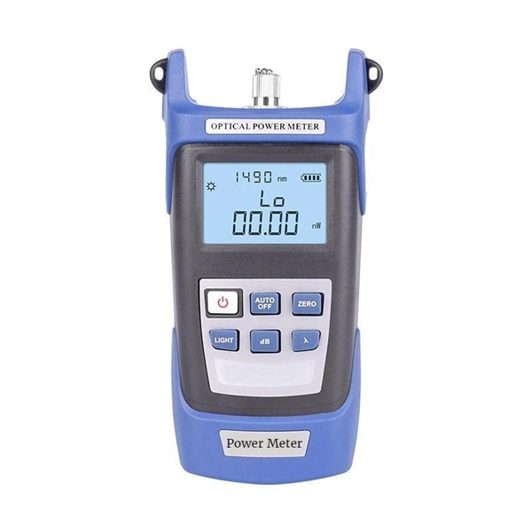
Wavelength measurement devices work on the principle of measuring the distance between two consecutive points of an electromagnetic wave in terms of wavelengths. This can be achieved through various methods, including spectrophotometry, interferometry, or the use of optical spectrum. These devices accurately determine the wavelength of light, providing crucial information for research, quality control, and diagnostics. Wavelength is a fundamental property of light and can significantly affect its interaction with matter. Precise wavelength measurement allows scientists to. Wavelength meters are interferometers used to measure wavelengths of laser beams. The devices are mounted on benches or desktops. They generate numerical values identifying pulsed and continuous wave lasers. They enable. This article provides a comprehensive explanation of the concept of wavelength in physics, particularly in optics and photonics. It defines wavelength as the spatial period of a wave, explaining its mathematical relationship to the wavenumber, optical frequency, and phase velocity. Accurate wavelength measurement is crucial in fields like physics, chemistry, astronomy, and engineering. Each method offers unique insights and varying degrees of precision.
[PDF]

However, there are still some scenarios where an optical drive is necessary or desirable. What is an Optical Drive?. THe Optical memory is an electronic storage medium that uses a laser beam to store and retrieve digital (binary) data. In optical storage technology, a laser beam encodes digital data on an optical disc or laser disc in the form of tiny pits arranged in a spiral pattern on the surface of the disc. In this article, we'll explore the pros and cons of having an optical drive and help you decide whether you need one. Although a number of optical formats have been used over time, the most common examples are optical discs such as the compact disc (CD) and the digital versatile disc (DVD). The primary components of an optical drive include a laser, a lens system, a motor for spinning the disc, and a decoder to interpret the data. It is commonly found in computers, laptops, and gaming consoles. Optical drives are essential for installing software, playing movies, and backing up data.
[PDF]

The optical module is usually composed of Transmitter Optical Subassembly (TOSA, containing a laser LD Chip), Receiver Optical Subassembly (ROSA, containing a photodetector PD Chip), a driving circuit, and an optical and electrical interface. Its schematic is shown in. This section explains the structure of a typical pigtail butterfly module, which gets its name from the two rows of seven leads at right angles on each side of the metal package plus an optical fiber pigtail at one end (Fig. Let's look at the internal structure (Fig. 2) of a common butterfly. Optical modules are devices used to connect network devices, transmit and receive data between network devices, and can be used to convert optical and electrical signals. The optical module is a very important component in an optical communication system. Optical devices are the core components of optical modules. TOSA and ROSA in Common Optical Transceiver Modules For ordinary optical transceiver modules, there are two optical devices, TOSA and ROSA, which have opposite effects.
[PDF]
The term 10G optical module generally refers to hot-pluggable transceivers in SFP+ form factor that support 10 Gigabit Ethernet (10GbE) transmission. A typical 10G SFP+ transceiver integrates a laser transmitter, a photodiode receiver, and a control IC within a compact housing. 10GBASE-LR is a 10-gigabit Ethernet optical standard that operates at 1310 nm over single-mode fiber (SMF), supporting link distances of up to 10 km. It is typically implemented using SFP+ transceivers and defined under IEEE 802. 10G-LR module has become one of the most widely. What is SFP? SFP refers to the small form pluggable factor. In actuality, it is a form of 10 Ethernet Transceiver that enables both: With these features, you can manage high data speed. The SFP works with small form factors (SFF) connectors that ensure high data speeds and physical compactness. So. As enterprises migrate to high-bandwidth environments, 10G optical modules remain one of the most widely adopted solutions for data centres, enterprise backbones, and metropolitan networks. However, facing the numerous models on the market, such as LRM, SR, LR, ER, ZR and other optical modules, how to choose the most suitable. High-speed data transmission in enterprise and data center networks is driven by 10G optical modules. Choosing the proper SFP+ module, whether it be SR, LR, or ER, can have significant impacts on performance, reliability, and costs.
[PDF]
MI is a 100% open source low-code integration solution with an AI-powered development experience. Build your integrations faster, and deploy them in an ESB-style or microservices architecture. Run them in the cloud, on-premises, or in hybrid environments. Looking for an Integration Platform as a. WSO2 Micro Integrator is a comprehensive integration solution that simplifies your digital transformation journey. The Micro Integrator streamlines connectivity among applications, services, data, and the cloud using a user-friendly, low-code graphical design experience. To learn more about WSO2. An integration project can be created as a Maven Multi Module (MMM) project by default. This enables you to add ESB Configs, Composite Exporter, Registry Resources, Connector Exporter, Docker Exporter, and Kubernetes Exporter as sub-modules to the project. This is a simple service orchestration scenario. It offers a powerful configuration-driven approach, allowing developers to build integration solutions graphically, with a user-friendly low-code graphical designing. The Micro Integrator is designed in a highly container-friendly manner, and thereby, it is ideal for you to use it for Microservices Architecture (MSA)-based solutions, which are deployed in container-based environments.
[PDF]

These installation instructions provide overview and specification information for small form-factor pluggable (SFP/ SFP+/SFP28) modules, as well as instructions for installing and removing the modules. Small form factor transceiver modules (including SFP, SFP+, and SFP28 modules) plug into the SFP. Some Extreme Networks switches support the use of 25 Gb SFP28 pluggable optical modules. Each module provides one 25-gigabit transmit and receive channel. Use of 25Gb SFP28 modules in QSFP28 ports requires the use of the QSFP28 to SFP28 adapter (part no. Use only Extreme Networks-certified. The ESR SFP28 module provides a 25 Gb optical connection using an LC duplex optical connector over one pair of OM3 or OM4 multimode fibers. One data lane operates in each direction, at 25 Gbps up to 200 meters using OM3 fiber or up to 300 meters using OM4 fiber. The fiber-optic SFP modules contain a laser that is classified as a “Class 1 Laser Product” in accordance. LINK-PP offers a full range of optical transceivers and SFP module for modern data centers, telecom networks, and enterprise infrastructures. Our portfolio spans data rates from 1G to 400G, including SFP, SFP+, SFP28, QSFP+, QSFP28, QSFP-DD, and OSFP modules, designed for both single-mode and.
[PDF]

This is a simple video showing how to install a 850nm fiber optic link using SFP transceivers between 2 10 Gigabit backbone switches. Covers transceiver inst. As a leading provider of fiber optic solutions, Weunion offers a wide range of SFP-compatible products, including optical transceivers, DAC/AOC cables, LC patch cords, and MPO/MTP assemblies. This guide explores the essentials of SFP connectivity, installation best practices, and how Weunion's. These transceiver modules are hot-swappable input/output (I/O) devices that plug into 100BASE, 1000BASE and 10GBASE ports (for SFP+), which connect the module port with the fiber-optic or copper network. This document contains these sections: The SFP transceiver modules are hot-pluggable I/O. An optical module is an optoelectronic conversion device that transmits data by converting electrical signals into optical signals. Common types of optical modules include SFP, SFP+, SFP28, QSFP, QSFP28, etc. Different types of optical modules have different performance parameters such as speed. The 1310 nm WWDM solution, 10GBASE-LX4, requires the use of a mode-conditioning patch cord on multimode fiber to achieve its specified range of operating distances. more Audio tracks for some languages were automatically generated. Learn more This is a simple. One of the most widely deployed optical solutions for short-distance 10G links is the multimode SFP+ transceiver, commonly referred to as a 10GBASE-SR module.
[PDF]
The main trade show for the large optical module industry is the Optical Fiber Conference (OFC), that is held annually in southern California. Other prominent shows for the industry include ECOC in Europe and FOE in Japan.
[PDF]
Connectorized attenuators often have a quite compact housing, essentially looking like a fiber-optic adapter. Some of these devices provide a fixed level of attenuation, quantified as the insertion loss in decibels. An optical attenuator, or fiber optic attenuator, is a device used to reduce the power level of an optical signal, either in free space or in an optical fiber. The basic types of optical attenuators are fixed, step-wise variable, and continuously variable. Optical attenuators are commonly used in. Fiber-optic attenuators are a specific type of optical attenuators which are used in fiber optics, e. for achieving a suitable signal level for a data receiver in a telecom system. It primarily ensures the power or amplitude of a signal is lowered without significantly distorting its waveform. The attenuator circuit will allow a known source of power to be reduced by a predetermined factor, which is usually expressed as decibels.
[PDF]
If you encounter any of these issues, check the optical connector for damage or dirt, inspect the fiber optic patch cord, ensure the optical module is correctly installed, and check the device settings for compatibility. Subsequently, the driver semiconductor laser (LD) or light-emitting diode (LED) emits modulated optical signals at the corresponding rate. After transmission through the optical fiber, the receiving interface converts the optical signals into electrical signals using a photodetector diode and. An optical module is a typically hot-pluggable optical transceiver used in high-bandwidth data communications applications. Optical modules typically have an electrical interface on the side that connects to the inside of the system and an optical interface on the side that connects to the outside. The Transmitter Optical Sub Assembly (TOSA) is responsible for the emission of light. Its primary function entails converting electrical signals into optical signals.
[PDF]
Essentially, an OXC is a device that allows for the interconnection of multiple optical fibers, facilitating the routing of optical signals from any input fiber to any output fiber. This functionality is crucial for managing the vast amounts of data transmitted through optical. An optical cross-connect (OXC) is a network device that switches high‐speed optical signals between fiber inputs and outputs without converting them to electronics. In the 1980s, when transmission speeds supported by optical fibers increased from 45 Mbit/s to 2. 5 Gbit/s, carrier networks. The Optical Transport Network has emerged as a dominant standard to address these needs, offering robust transmission, multiplexing, switching, and management capabilities for optical signals. Compared with traditional ROADM based on separate boards and inter-board fiber patch cords, OXC uses integrated interconnections to build an all-optical switching resource pool, achieving highly integrated, fiber. Optical Cross-Connects (OXCs) are critical components in modern optical networks, enabling the switching of optical signals between different paths without the need for electrical conversion. This technology supports scalability, flexibility, and high performance for backbone networks, data‑center interconnects, and next-generation mobile.
[PDF]
Remove the module from the receiver frame. Use the Allen wrench to remove the module cap screws located at the top, middle and bottom of the module (Figure B). For 37 and 16/16 position use a Phillips screw driver to remove the (2) 2-56 screws. Terminating fiber optic cables essentially means putting connectors on fiber optic cable so that you can connect the cable to various devices or network components. Think of it as the equivalent of connecting the dots in a complex puzzle; without proper termination, the whole system can break down. How to remove/disconnect fibre cable from Telus modem? Pull the green thing from the metal thing If you pull it out make sure to put the fiber connection in a plastic bag or blow it with air before plugging it back in, Fiber laser modules and a single spec of dust/lint/crumb can affect your speeds. Terminating fiber optic cable is a crucial step in the installation process, as it ensures a reliable and efficient connection. The contact can only be installed from one side. Ensure that the contact is squared up with the corresponding module location. Once in place, pull the wire. The transceivers for the router are hot-removable and hot-insertable field-replaceable units (FRUs). After you remove a transceiver or when you change the media-type configuration, wait for 6. IN THIS VIDEO I WILL SHOW YOU How to Disconnect Optical Fiber Cables from the Connector #DISCONNECTOPTICALFIBER.
[PDF]
The single-fiber optical module has only one optical fiber port, and only one optical fiber can be inserted to transmit and receive optical signals at the same time. One fiber is required for. Single fiber modules (BiDi) use one fiber for both transmitting and receiving data. This saves space and money. Dual fiber modules use two fibers. They are easier to set up and give steady communication. It uses WDM technology to realize the bidirectional transmission of optical signals on one optical fiber. BIDI module only has 1 port, wave filtering through the filter of module, and finished the transmitting of 1310nm optical signal. Appearance and use: single fiber optical module has one optical fiber interface, which connects one optical fiber; dual-fiber optical module has two optical fiber interfaces, which connect two optical fibers; 2.
[PDF]