If you encounter any of these issues, check the optical connector for damage or dirt, inspect the fiber optic patch cord, ensure the optical module is correctly installed, and check the device settings for compatibility. Subsequently, the driver semiconductor laser (LD) or light-emitting diode (LED) emits modulated optical signals at the corresponding rate. After transmission through the optical fiber, the receiving interface converts the optical signals into electrical signals using a photodetector diode and. An optical module is a typically hot-pluggable optical transceiver used in high-bandwidth data communications applications. Optical modules typically have an electrical interface on the side that connects to the inside of the system and an optical interface on the side that connects to the outside. The Transmitter Optical Sub Assembly (TOSA) is responsible for the emission of light. Its primary function entails converting electrical signals into optical signals.
[PDF]

Beam splitters are classified by construction (plate, cube, pellicle, polka dot) and by function (standard, non-polarizing, polarizing, dichroic). Construction determines ghosting, damage threshold, and form factor. Function determines how polarization and wavelength are. Beamsplitters are optical components used to split incident light at a designated ratio into two separate beams. Additionally, beamsplitters can be used in reverse to combine two different beams into a single one. Beamsplitters are often classified according to their construction: cube or plate. A beam splitter (or beamsplitter, power splitter) is an optical device which can split an incident light beam (e. a laser beam) into two (or sometimes more) beams, which may or may not have the same optical power (radiant flux). It is a crucial part of many optical experimental and measurement systems, such as interferometers, also finding widespread application in fibre optic telecommunications. It is also possible to combine the separated beams. Types of Beam Splitters 2. They are found in different configurations and can be used in multiple applications. However, how they work exactly often remains overlooked. These versatile tools can split both laser and regular light, depending on the application in question.
[PDF]

This guide will walk you through the process of checking photo sensors using a multimeter, covering various types of photo sensors, the necessary tools and safety precautions, and the specific measurement techniques involved. Knowing how to effectively use a multimeter to test photo sensors can save you time, money, and frustration when dealing with malfunctioning devices. more What is a Voltage Divider? | What is a Voltage. Before replacing the sensor or fixture, it's efficient testing it first, With a few tools and a step-by-step process you can find whether your outdoor lighting control system is working as intended or if the problem lies elsewhere. In this complete guide from Lead-Top, a global leader in photocell. In this blog post, we explain step-by-step how to troubleshoot a sensor with a digital multimeter (DMM). Here are the steps: Troubleshooting a sensor measurement failure requires mechanical tools to uncover the protective shields or components so you can reach the sensor in question. Always follow the manufacturer's instructions for the sensor and multimeter. Ensure the sensor is properly connected to the multimeter and. A multimeter is an indispensable diagnostic tool for anyone working with electronics, electrical systems, or indeed, sensors. It's a versatile device capable of measuring voltage, current, and resistance, providing crucial insights into the health and functionality of electrical circuits and.
[PDF]

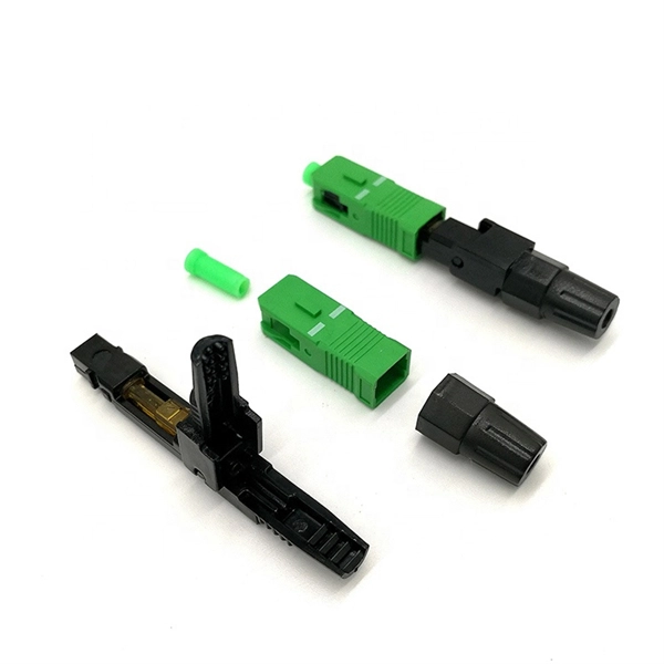
A fiber-optic splitter, also known as a beam splitter, is based on a quartz substrate of an integrated waveguide optical power distribution device, similar to a coaxial cable transmission system. The optical network system uses an optical signal coupled to the branch distribution. The fiber optic. In the backbone of modern Fiber-to-the-Home (FTTH) networks, optical splitters serve as the unsung heroes that enable cost-efficient connectivity for millions of subscribers. By dividing a single optical signal from a central Optical Line Terminal (OLT) into multiple outputs for Optical Network. Optical splitter, also called optical beam splitter, is an integrated waveguide optical power distribution device that can split an input optical signal into two or more output optical signals, and the optical input power is evenly distributed on all output ports. For example, an optical splitter. The answer lies in a small device. We call it an Optical Splitter. This device is the heart of Passive Optical Networks (PON). It allows service providers to save money. It helps them distribute bandwidth efficiently. In this article, we explain the definition, working principles, types, and. An optical splitter is a device that divides light transmission in a network into multiple output ends. It plays a crucial role in facilitating network interconnections.
[PDF]

The core measurement procedure follows five steps: Turn on the meter and let it warm up. Most meters need a brief stabilization period before readings are reliable. Check your model's manual, but a minute or two is typical. Set the wavelength to match your light source. Fiber loss is the difference between the power when light is coupled from the transmitting end to the fiber and the power when the light reaches the receiving end. Generally speaking, when measuring the. An optical power meter measures the strength of light traveling through a fiber optic cable, giving you a reading in dBm (decibels relative to one milliwatt). The basic process is straightforward: turn the meter on, set it to the correct wavelength, clean your connectors, plug in, and read the. A power meter and light source are essential test tools that work in tandem to measure fiber optic cable loss and evaluate the quality of optical links. They provide the data necessary to quantify signal loss and pinpoint issues that could impact network performance. Here's how they work: A power. You measure optical power in dBm or insertion loss in dB. Verify light travels from transmitter to receiver. We'll give you the basic information you need and provide some printable references.
[PDF]

Average Optical Power: How bright the light is (measured in dBm). Too dim? Your signal gets lost in the fiber. Extinction Ratio: The difference between “on” (1) and “off” (0) light power. A higher ratio = cleaner signals. Transmitter Side: An electrical signal hits a laser diode (LD) or LED, which spits out light. Receiver Side: Light enters a photodetector (like a tiny solar cell), which turns it back into electricity. A built-in amplifier boosts the signal for your. The average transmitted optical power refers to the optical power output by the light source at the transmitting end of the optical module under normal working conditions, which can be understood as the intensity of light. In communication, we usually use dBm to represent optical power. However, in practical use, we adopt the average Tx power. The transmission power is related to the. This article provides an in-depth analysis of two key performance indicators of optical modules: transmitter power and receiver sensitivity. Transmitter power characterizes the average optical power output from the laser under rated conditions, while receiver sensitivity indicates the minimum. An optical module is a connecting module that serves as an optical-electrical conversion device. At the receiver end, the optical signals are reconverted into electrical.
[PDF]
At Multilink, we offer traffic power solutions to keep traffic signals, camera equipment, illuminated street signs and other tech up and running. Power traffic signals, camera equipment, lighting and other t.
[PDF]
In general, foreign suppliers enter the Chilean market by appointing an agent, distributor, or wholesaler. Most are small-to-medium size firms. Several large firms handle different product lines and operate a.
[PDF]

Optical isolators utilize retarders to prevent unwanted reflections, while optical attenuators adjust light intensity by varying polarization alignment. Polarization rotators and variable beam splitters allow controlled redirection of light for applications in optical systems and. Thorlabs offers an all-in-one attenuator that will reduce brightness as well as accentuate contrast. This gives the user much finer control of the image brightness compared to a standard fixed-transmission filter. When the polarizer transmission axes and input polarization are parallel, the. We propose and demonstrate a polarization-insensitive silicon photonic variable optical attenuator. The designed device uses a two-dimensional apodized grating coupler as a surface-normal coupling interface, which has the advantages of low-cost fiber packaging and polarization insensitivity. Boston Applied Technologies' Polarization Maintaining Variable Optical Attenuator (PM-VOA) maintains constant polarization output regardless of wavelength and level of attenuation. Based on the. MEMS attenuators (MEMS VOAs) are based on a micro-electro-mechanical system (MEMS) technology. It is a micro-optic component designed for next generation, dynamically configurable optical networks. The. Figure 1. 1 For narrowband VOAs, turning the adjustment screw moves the blocking device up and down in order to achieve the desired attenuation.
[PDF]

Its red laser shines through most yellow-jacketed optical fibers to help you pinpoint breaks, bends, faulty connectors, splices and other causes of signal loss. It has a reach of up to 5 km. The RPEN-210 is a necessity tool that should not be missing from any fiber plant manager or fiber optic installing technician. The Visual Fault Locator (VFL) Pen has a visible red light source centered on 650nm. Tool sends visible light over a fiber strand with a 10mW power, good enough to reach. The FLS-140 is the easiest way to identify optical fibers from end to end and locate polished connector endfaces. 5 dBm, but it couples approximately 3 dB less into a fiber. This is a Class 1 unit; the Class 1 limit is +3 dBm. The Class 1 limit (+3 dBm/2 mW) is intrinsically safe in all circumstances and is. This VFL has a fiber stub; its total emission is -1. 30 years of experience in R&D and manufacturing - Jilong JILONG launched the VFL-22M mini red light pen, pocket design, small and portable, integrated VFL/LED function, strong and stable light source, strong penetrating. A visible laser radiation source is one of the simplest devices and is designed to produce red light with a wavelength of 650 nm, which is transmitted through an optical fiber. The main purpose of this device is to locally detect various types of damage (such as breaks, bends, poor splicing, etc.
[PDF]
Main Source of Lighting for Household by District, Region, and Type of Locality. PxWeb Mark your selections and choose between table on screen and file format. Marking tips Ghana Statistical Services ©2024 | Terms & Conditions. It's helps to drag strangers and robbers from your house when you're away. - 3MP HD Image: The security camera light bulb with 3MP super HD image,let you see the every details. This Lethe battery powered twin security light features a PIR sensor which is a great deterrent for. Dummy security. With over 20 years of experience in the industry, Response has a proven track record of providing high-quality remote monitoring services for our clients. Through the use of advanced technology, we are able to monitor clients' properties 24/7 and receive real-time alerts whenever an alarm is. Buy Remote Home Monitoring Systems Online from Jumia Ghana - Choose from Our Collection of Remote Home Monitoring Systems and Shop them at the best price. Enjoy Cash On Delivery | Secure Payment | Free Returns & more!. 24/7 remote security monitoring and rapid response services. Our experienced team uses the latest techniques and quality materials to. The company offers a comprehensive cloud-based Teleradiology-Platform-As-A-Service (TPaaS) that facilitates secure and efficient management of medical images, making it highly relevant for remote monitoring in healthcare.
[PDF]
Lighting Control System | Smart Lighting Wiring Setup | Full Guide In this video, you will learn how to connect and install a Lighting Control System step-by-step. This guide covers wiring setup, switch modules, dimming control, sensor setup and panel . as a guide for proper and reliable installation. The mounting location should e selected and prepared based on the application. All electrical wiring and mounting hardware (i. ) should be prepared with consideration of the requirements o cuit breaker before. Intelligent Lighting Controls' installation guides provide detailed instructions on how to install all of our solutions. The Lightolier Controls Optio Lighting Control Panels are high-performance, wall mounted lighting control panels which offer a wide range of dimming and relay modules to accommodate any lighting control application.
[PDF]

Solid Green: The ONT is powered on and functioning normally. What to check: Make sure the power cable is securely plugged into both the ONT and a working wall outlet. If you're using a power strip, check that it's turned on. Learn what each light on your fiber equipment means—from power and fiber signal to Ethernet and phone service—and how to quickly troubleshoot issues. This light shows whether your ONT is getting power. No Light: The ONT is not receiving. The Optical Network Terminal (ONT) is a crucial device in modern telecommunications, serving as the interface between your home network and the fiber-optic internet connection provided by your Internet Service Provider (ISP). The ONT has a series of lights that indicate its status and any potential issues. In this article, we will delve into. Power down for 15mins then power back on and wait 3mins for the lights to settle Power connector has come loose. Problem with the plug socket. Optical: This should be a solid green at all times (If the power light is off, this will also. This guide is designed to offer an explanation on how to troubleshoot issues with a CityFibre ONT (Optical Network Terminal). For more help topics, please visit the main Support Page. If you would like details on Freeola Broadband tariffs using the CityFibre Network, please visit our Broadband. You can use the status lights on your optical network terminal (ONT) to help find and fix internet issues. An ONT may also be called a Service box.
[PDF]
Visible light communication (VLC) is an advanced, highly developed optical wireless communication (OWC) technology that can simultaneously provide lighting and high-speed wireless data transmission. A VLC system has several key advantages: ultra-high data rate, secure communication channels, and a. In some situations, visible light communication (VLC) has considerable advantages over the more generally utilized radio frequency (RF). This chapter delves into the fundamentals of VLC, beginning with an insightful exploration of its background and subsequently addressing the advantages and. Efficiency, durability and long life span of LEDs make them a promising residential lighting equipment as well as an alternative cheap and fast data transfer equipment. Appliance of visual light in data communication by means of LEDs has been densely searched in academia. In this paper, we explore. Visual light source of Lano Technology is designed to meet the demands of various industries, our visual light sources deliver exceptional brightness and clarity, ensuring optimal visibility for your applications. With a wide range of product models available, you can find the perfect solution for. Below find pdf documentation available for Visual Lighting. You can also view the Visual Lighting Manual in web help format. Visual is powerful lighting software engineered to bring.
[PDF]

It emits a stable red light driven by a constant current source, which is coupled into the optical fiber through an interface to perform fiber fault detection functions. These include checking fiber connectivity and locating faults such as fiber breaks and bends. The B5 Rechargeable Red Light Pen is a professional 650nm visual fault locator designed for fiber optic network maintenance, installation, and troubleshooting. Its advanced rotary automatic lift laser head ensures smooth operation, while the integrated LED lighting improves visibility in low-light. Luxbond LBTEK Fiber Optic Red Light Pen (also known as a pen-style visual fault locator or fiber optic fault detector) uses a 650 nm semiconductor laser as the light source. Note: Meant for use with polished, terminated fiber cables. Always insert and remove the fiber connector without bending the connector to avoid breaking. The RPEN-210 is a necessity tool that should not be missing from any fiber plant manager or fiber optic installing technician. The Visual Fault Locator (VFL) Pen has a visible red light source centered on 650nm. Tool sends visible light over a fiber strand with a 10mW power, good enough to reach. ● Practical Design: Small size and lightweight, pen-type design with pouch make it portable. Design with a stainless steel head and aluminum body to prevent crash and dust, the case ground design prevents ESD damage efficiently Temp. Only registered users can write questions.
[PDF]


