* Bronze alloy bolts shall have a minimum tensile strength of 70,000 pounds per square inch. ** Bolts, cap screws, nuts, flat washers, locknuts: 18-8 alloy. Qualified to meet or exceed all the nationally recognized standards, including ANSI C119. 4 and NEMA CC1, the DMC Power system raises the quality, safety and productivity standard. Other aluminum compression connectors are made from com-mercially pure high conductivity wrought aluminum. Select type of connector from those listed below and follow the indicated procedure. ** Belleville Washers: 302 alloy. EX: TPC600-4N4-AA-GS TYPE TPC-N-AA Terminal Connector A C FIG. 3 T Terminal is designed to connect to aluminum or copper pads. Pad conforms to NEMA standards. 56 © 2011, AFL, all rights reserved. PP-3-00479. This publication contains the following new or updated information. This list includes substantive updates only and is not intended to reflect all changes. Added information about using a Top Hat Rail, catalog number 141A-AHR45, with a Adapter Extension Module, catalog number 141C-X40. Examples. We have recently reviewed our company's bus torque chart and found some of the values are in line with the bolt mfg suggestions (i. - 1/2" - 3/4" bolts). I started to update our torque chart to match the.
[PDF]
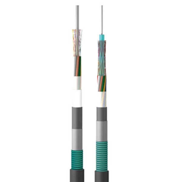
In this comprehensive guide, we'll walk through the best practices for installing various types of fiber optic cable, from patch cords to distribution fiber, and provide practical tips to ensure a successful installation. Correct patch-cord installation is essential for maintaining low insertion loss, stable return loss, and long-term reliability in both indoor and outdoor fiber networks. Proper handling, routing, cleaning, bend-radius management, and connector alignment ensure that the optical link meets design. Proper installation and regular maintenance of fiber optic patch cords play a crucial role in achieving optimized network performance, preventing signal errors, and extending service life. This guide addresses expert-certified best practices applied by professionals in the telecommunications, data. Proper connection of fiber optic cables is essential to harness these benefits fully, as even minor errors can lead to significant performance issues like signal loss. Whether you're connecting a data center, a corporate network, or a high-density fiber infrastructure, correct installation methods are essential. Yingda. In today's high-performance networks, fiber optic patch cables are the lifelines that ensure smooth data flow across switches, servers, and routers. Even the most advanced optical transceivers can only perform at their peak when paired with properly installed, clean, and precisely managed fiber.
[PDF]

Its typical transmission distance is 20km or 40km. For instance, some ethernet switch manufacturers refer to the 1000BASE-LH SFP as the 1G 1310nm 40km SFP transceiver, which indicates the module's transmission distance and wavelength. The 10G SFP+ dual-fiber optical module is a small pluggable optical transceiver that adopts a dual-fiber bidirectional design. It completes signal transmission (Tx) and reception (Rx) through two independent optical fibers, ensuring the stability and reliability of signal transmission. An SFP (Small Form-factor Pluggable) module transmits data over fiber using specific wavelengths and power levels, which directly influence how far the signal can travel before degradation occurs. This is why two. If the optical module works at a wavelength near 850nm (880nm) or 910nm (940nm), then the module is a multi-mode fiber (MMF) optical transceiver, and if the working wavelength is 1310nm or 1550nm, it is a single-mode fiber (SMF)optical module. Generally, the maximum transmission distance(generally. The transmission distance of optical transceiver modules is divided into short distance, medium distance, and long distance. A 1-core module uses a single fiber core for data transmission, while a 2-core module uses two cores. o Think of a highway. Chromatic dispersion This is a key factor affecting single mode fiber distance.
[PDF]
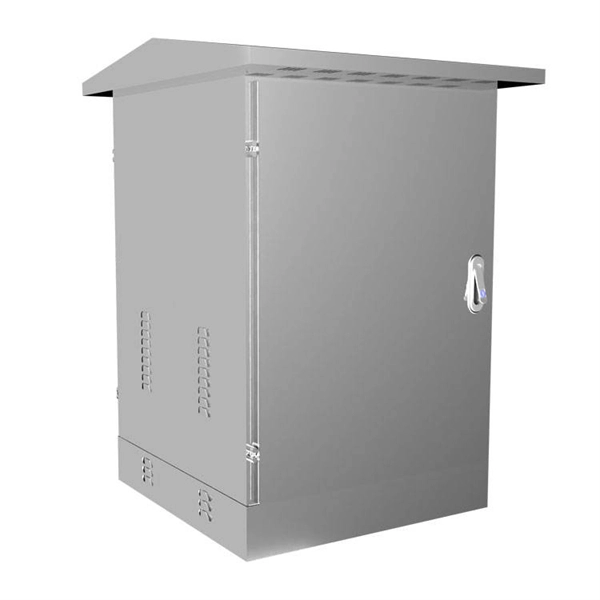
In this step-by-step tutorial, we'll cover: ✅ Tools you need ✅ Safety precautions ✅ Mounting the box ✅ Wiring tips ✅ Final checks Perfect for beginners, DIYers, and electricians who want a clear installation guide. more Learn how to properly install an electrical. Learn how to install a distribution box safely and correctly. Covers wiring, placement, standards, and expert tips for a compliant setup. A distribution box is the heart of any electrical system. It takes the incoming power and safely distributes it to different circuits throughout your building. Before starting the installation, finding a proper place for putting the distribution box is crucial, because it largely decides the safety and convenience of maintenance. Let's see what factors need to be taken care of when choosing the installation place. Whether it is residential buildings, commercial facilities or industrial sites, the. Dear Mr. Electrician: How do I install an electrical box in a narrow space? NOTE: Text links below go to applicable products on Amazon. As an Amazon Associate, I earn from qualifying purchases. Using my links helps to keep this website FREE. Warm reminder: Do not disassemble or modify without experience and professionals. Select location Before.
[PDF]

Recommendation ITU-T G. 654 describes the geometrical, mechanical and transmission attributes of a single-mode optical fibre and cable which has the zero-dispersion wavelength around 1300 nm wavelength, and which is loss-minimized and cut-off wavelength shifted at around the 1550 nm. Recommendation ITU-T G. 649 Optical fibre cables G. 659 Characteristics of optical components and subsystems Characteristics of optical systems G. E fibre: empowering ultra high-capacity long-haul transmission. Sumitomo Electric. TRANSPORT A S ACCESS NE around the 1550 nm wavelength region. This is the latest revision of this Recommen. ata rates at and above 800 Gb/s over distances further than a few hundred kilometres. Over longer distances, such as between two data centres, signal regeneration or addition ng-distance transmission,” said Xavier Renard, Telecom Marketing Di ector at ACOME. “It's also c ucial that we consider the. ACOME Group and Sumitomo Electric Industries, Ltd. have announced a new proposal for long-haul optical network cables that will 'break through the glass ceiling' of data transmission limits to ensure the ever-growing demands of data centres can be supplied. To support these high capacity systems in terrestrial backbone networks, low attenuation and large core area fibers compliant with Recommendation ITU-T G 654. E were introduced and have been extensively deployed worldwide.
[PDF]

Dispersion of an optical fiber directly affects the bandwidth and distance capability of the fiber optic link and reduces its efficiency. The higher the dispersion, the lower the potential data rate and transmission distance. Fiber optic cable transmission distance is determined by two primary physical factors that affect signal quality as light travels through the fiber medium. The greater the distance, the greater. With amplifiers, such as Erbium-doped fiber amplifiers (EDFAs), the distance can be extended to 600 miles or more, and even further with additional amplifiers for long-haul applications. In this guide, we'll explore how fiber optic cables function, the maximum distances for different types of fiber optics, and tips for. Fiber optics transmits information by sending light signals through thin strands of glass. While this technology offers higher speeds and longer distances than traditional copper wiring, physical limitations impose distance constraints. Light pulses degrade as they travel over long spans, primarily. The maximum distance a fiber optic cable can transmit data reliably is influenced by several key factors, primarily the inherent properties of light and the physical characteristics of the fiber itself. Understanding these limitations is essential for designing efficient and robust internet.
[PDF]
Whether you're installing new fiber optic cables or troubleshooting and repairing an existing fiber network, a working knowledge of the regulations that apply to your project can help you (and your team) stay s.
[PDF]
If unavoidable, the distance should be no less than 500 mm, and a corrosion-resistant partition should be used. Failure to maintain sufficient spacing can result in several critical issues that could affect the safety and functionality of the installation. Let's explore why this. AFTER FIREPROOFING AND INSULATION IS INSTALLED 4. NOMINAL MINIMUM SEPARATION BETWEEN CONDUITS OF REDUNDANT ELASS IE DIVISIONS IS C INCHES LE MANI ERRATE REDUCED TO | INCH FOR CONDUITS ROUTED THROUGH WALL AND FLOOR PENETRATIONS, AND ON CONCLIIT RUNS WHERE THE SEISMIC ATTACHMENT CRITERIA, AS SHOWN. en completely installed, without damage either to conductors or structural system use maintain spacing or to keep cables in place when the tray is ect the minimum bend ra-dius for cables as they exit the bottom of the cable tray. The NEC requires that cable trays must be supported by members at an interval specified by the cable tray manufacturer, but not more than 5 feet for horizontal runs to support the weight of the cables and other loads. The NEC has a requirement for ladder-type cable trays. The rungs cannot be more. IEEE Guide for the Design and Installation of Cable Systems in Substations IEEE Std 525™-2007 (Revision of IEEE Std 525-1992/Incorporates IEEE Std 525-2007/Cor1:2008) IEEE Guide for the Design and Installation of Cable Systems in Substations Sponsor Substations Committee of the IEEE Power.
[PDF]
