In the following tutorial, we will show how to wire 120V single-phase and 240V split-phase circuit breakers and loads inside a residential main panel. The figure below shows a typical breaker panel used for 120V and 240V circuits. Messy distribution boxes are dangerous and very hard to fix. You will learn to build a safe, efficient, and professional electrical system today. Circuit breaker wiring configurations involve organizing main switches, busbars. A breaker box, also known as a circuit breaker panel, is an essential component of any electrical system. It is responsible for distributing electricity throughout a building, ensuring that each circuit receives the proper amount of power. To understand how a breaker box works, it is helpful to. Each circuit is protected by a circuit breaker, a safety device that automatically shuts off power if it detects an overload or a fault. If you're looking to replace an old fuse box replacement or upgrade your home's power capacity, you'll be dealing with the load center or service panel. The distinction between 1P and 2P circuit breakers plays a pivotal role in determining the appropriate protection level for various circuits. When installing or troubleshooting a power distribution system, understanding how to correctly connect the main electrical supply to the control panel is crucial.
[PDF]

The following tutorial explains how to wire a 120V single-phase breaker and load points in a residential panel. 120V single-phase circuits are commonly used in homes for lighting and receptacle outlets. Plastic is lighter and good for indoor setups. Choose based on where you'll install the box. Inside the box, you'll find things like circuit breakers, busbars, terminal blocks, and wires. These parts control and distribute the electricity to different circuits safely. Some boxes also include DIN. The electrical service panel, often called a breaker box, acts as the central distribution point for all electricity entering a home. Whether you are an electrical contractor or a construction brigade, knowing how to properly and safely install distribution boxes is the basis of ensuring the safe operation of the entire system. This article details the process of installing them, which helps you comprehend distribution boxes. No description has been added to this video. Enjoy the videos and music you love, upload original content, and share it all with friends, family, and the world on YouTube. Jesse Kuhlman is a Master Electrician and the Owner of Kuhlman Electric based in Massachusetts. Jesse specializes in all aspects of home and residential wiring, troubleshooting, generator installation, and WiFi thermostats. Jesse is also the author of four eBooks on home wiring including.
[PDF]
The state of a laser's polarization is determined by several anisotropic mechanisms of either the laser gain media or the resonator. "Anisotropic" refers to properties whose values vary in different direct.
[PDF]
In this comprehensive guide, we'll walk through the best practices for installing various types of fiber optic cable, from patch cords to distribution fiber, and provide practical tips to ensure a successful installation. The processes. Fiber optic installation delivers unmatched network performance for modern businesses, providing greater bandwidth capacity and superior resistance to electromagnetic interference compared to traditional copper cables. Professional installation ensures optimal performance and higher reliability for. In the spirit of self-reliance and technical mastery, we've crafted this detailed guide to empower you to take control of your own network by installing fiber optic cables yourself. In this guide, we will walk you through a step-by-step process for the installation of fiber optic cables. The number one cause of signal loss in optical fiber installations is dirt on. In this comprehensive guide, we'll cover everything you need to know about fiber optic cabling—from key components and installation procedures to best practices for network design and maintenance. What is Fiber Optic Cabling? Fiber optic cables transmit data as pulses of light through strands of.
[PDF]

Step-by-step instructions on how to install the Polylok 12" distribution or drainage box. Installing a distribution box is a crucial step in the setup of a septic system, serving as the central hub that directs wastewater from the septic tank to the drain field. This component ensures that effluent is evenly distributed across the leach field, preventing overloading and potential system. maintains a relatively low soil loading rate and provides better effluent treatment. Distribution boxes also provide a readily accessible means of locating the leaching device, making flow adju e typically made of reinforced concrete with plumbing “knock outs” into th box. Frequently-asked questions and answers about septic system distribution boxes or D-boxes: what is a D-box, where is the D-Box, why do we need a D-box, and how do I fix or replace a D-box? In this article series about septic system drop boxes we describe the best procedures for locating and. When installing, please follow the instructions strictly and ensure installation by a professional. Open the terminal chamber cover, connect the cables through the cable gland to the terminals, ensuring both the internal and external ground wires are correctly connected. After confirming there. **I. Installation methods for distribution boxes**1. **Preparation before installation** - **Tool and material preparation** - Prepare the tools requir.
[PDF]

This publication shows how to wire and install the 4010-9825 24V Distribution Block into a 4010 Fire Alarm Control Panel (FACP). Refer to the 842-058 Field Wiring Diagram for additional wiring information. 1 Transformer connection: Two red wires connect to AC 220V input port, while two yellow wires connect to AC input port of main board (had connected by the factory. 2 DC12V battery connection: Red wire on the circuit main board connects to the positive pole of acid-lead battery while black. Notify the carrier and call Telect's Customer Service Department at 1-800-551-4567. Keep the container until you have checked equipment operation. Use the original, undamaged container if you are instructed to return. Learn how to wire a distribution box step by step! This video shows real on-site footage of electrical installation, demonstrating safe and standardized wiring methods used by professionals. Such a system, however, does not assure. Material preparation: Prepare the required circuit breakers, wires, wiring ties and other materials, and ensure that they meet the design drawings and installation requirements. Location determination: Determine the installation position of the circuit breaker according to the position of the.
[PDF]
Check for proper IP/NEMA ratings and material quality. Ensure safe placement: install in dry, accessible areas with good ventilation and at appropriate height (typically ~1. Practice good wiring: secure grounding, neat cable management, proper insulation, and correct wire gauge. In this video, we'll walk you through the process of wiring a home distribution box with a detailed connection diagram. Whether you're an electrician or a DIY enthusiast, this guide will help you understand the basics of home electrical distribution. more Welcome to our channel! In this video. However, the key to a safe and reliable system lies in proper installation. If it's done poorly, you risk short circuits, fire hazards, or system failure. Done right, it ensures safety, compliance, and long-lasting performance. In this guide, we'll break down everything you need to know to install. Distribution board is a safe system designed for house or building that included protective devices, isolator switches, circuit breaker and fuses to safely connect the cables and wires to the sub circuits and final sub circuits including their associated Live (Phase) Neutral and Earth conductors. Learn how to wire a single-phase household distribution box in just 60 seconds! In this quick tutorial, we'll cover the essential components and wiring steps for a safe and efficient distribution setup in residential areas.
[PDF]
The development of high-performance twisted pair cabling and the popularization of fiber optic cables also drove significant change in the standards. These changes were first released in a revision C in 2009 which has subsequently been replaced by revision D (named ANSI/TIA-568-D).OverviewANSI/TIA-568 is a for cabling for products and services. The title of the standard is Commercial Building Telecommunications Cabling Standard a. ANSI/TIA-568 was developed through the efforts of more than 60 contributing organizations including manufacturers, end-users, and consultants. Work on the standard began with the. ANSI/TIA-568 defines system standards for commercial buildings, and between buildings in campus environments. The bulk of the standards define cabling types, distances, connectors, cable syste.
[PDF]
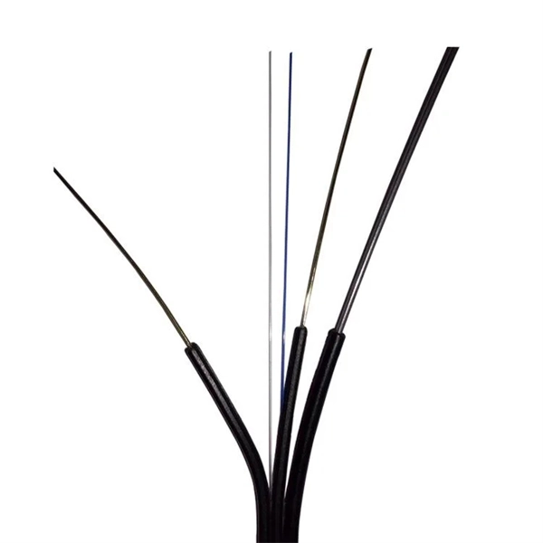
The color sequence for 24-fiber optic cables is: composed of 4 tubes, each containing 6 fibers with the colors blue, orange, green, brown, gray, and white. The TIA/EIA-598-C standard is the most widely followed guideline for color coding in optical fiber cables, both for loose-tube and. The color sequence of optical fibers in loose tubes (Chinese National Standard fiber order) Common fiber optic cables include 4-fiber, 12-fiber, 48-fiber, 96-fiber, and 144-fiber cables. The color sequence for 12-fiber. The chromatographic arrangement of the loose tube within a general fiber optic cable and the chromatographic arrangement of the fiber within the loose tube is shown below: 1. Cores in Tube. Available in OS2/OM3/OM4 at factory-direct wholesale pricing. How to Identify Fibers in High-Count Cables (>12 Fibers) For cables with more than 12 strands (e., 48, 96, or 144 fibers), the industry uses a “Tube and Fiber” system. It is the cornerstone of virtually all high-bandwidth, long-distance communication networks today. A standard communication-grade optical fiber is a double.
[PDF]

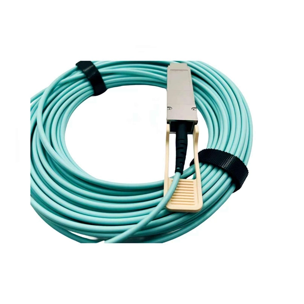
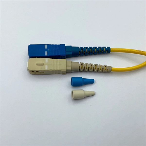
The goal is to fuse the two fibers together in such a way that light passing through the fibers is not scattered or reflected back by the splice, and so that the splice and the region surrounding it are almost as strong as the intact fiber. Fusion splicing is the process of fusing or welding two fibers together usually by an electric arc. Fusion splicing is the most widely used method of splicing as it provides for the lowest loss and least reflectance, as well as providing the strongest and most reliable joint between two fibers. Fiber Stripping: Selecting Precise Tools and Techniques Selecting the appropriate stripper will depend on the fiber coating diameter. This will typically be 250µm for bare fibers and 900µm for coated fibers. Reputable companies like Jonard, Fujikura, and INNO provide multi-hole strippers calibrated. Fiber misalignment and fiber geometry mismatch (e., core size, core-to-clad concentricity, core and cladding non-circularity, numerical aperture, etc. ) can result in real power loss across a splice joint. However, differences in the backscattering coefficients between two fibers can also show up. Fiber splicing means joining two optical fibers (permanently or temporarily) such that light guided in one fiber and reaching the joint (splice) can be transferred into the second fiber with low insertion loss.
[PDF]

In this guide, we'll break down everything you need to know to install a distribution box correctly and confidently. Choose the right box based on environment (indoor/outdoor), load capacity, and durability. Check for proper IP/NEMA ratings and material quality. Ensure safe placement: install in. This method statement will help the electrical engineers and supervisors for the installation of distribution board for an electrical project. Additionally site team will need detailed information of all aspects associated with the installation process in order to complete the job inline with the. h error or omission is the result of negl ion for commercial installations has changed in the last few years. There is a demand for more RCD protection of final circuits, affect Type B MCB distribution boards and their protective d bar arrangement designed to accept single and/or double pole OCPDs. ntact Cooper Lighting Customer Service at 1-800-573-3600. The most up to date version of this insta ecification sheet for weight and wind loading (EPA) data. Cable glands and lugs, 2. Applicable Location 3. Respective electrical rooms, LV. Installing a distribution box is a crucial step in the setup of a septic system, serving as the central hub that directs wastewater from the septic tank to the drain field. This component ensures that effluent is evenly distributed across the leach field, preventing overloading and potential system.
[PDF]
A grid networks consist of an interconnected grid of circuits, energized from several primary feeders through distribution transformers at multiple locations. Grid networks are typically featured in.
[PDF]
This schematic details the products and procedures for the treat-ment of construction joints/cold joints in new concrete structures. Cold joints occur when a fresh concrete batch is poured against a partially hardened existing layer. As you know, concrete hardens through chemical reactions between cement aggregate, water, and air. This detail uses two elements in addition to ad-ditives and coaings to waterproof. Cold jointing concrete is a technique used to connect two separate concrete pours that have not fully bonded together, often due to delays or interruptions in the pouring process. This method involves preparing the existing concrete surface by cleaning and roughening it, applying a bonding agent to. Eng-Tips is the largest forum for Engineering Professionals on the Internet. Members share and learn making Eng-Tips Forums the best source of engineering information on the Internet! Congratulations GregLocock on being selected by the Eng-Tips community for having the most helpful posts in the. Managing cold joints is an important concept to grasp when working on concrete projects. For the completed structure to be strong and long-lasting, cold joints must be handled correctly. The term "cold" is used because the two concrete layers are not bonded properly, which can result in a weakened.
[PDF]
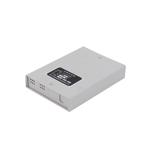
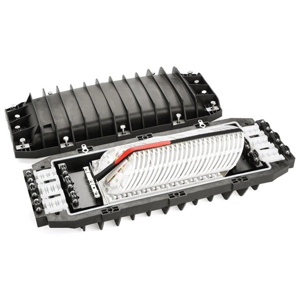
In network cabling, outdoor connections generally use fiber optic cables. When these optical fibers are installed or laid out, a Fiber Termination Box, or FTB, is used to distribute and protect the optical fiber link.
[PDF]

The formula for calculating electrical box size is: . The formula for calculating electrical box size is: . Free electrical load calculation tool for residential and commercial buildings. Calculate service entrance sizing, panel loads, demand factors, and ensure NEC Article 220 compliance. Important: Load calculations must comply with NEC Article 220 and local codes. Always verify calculations with a. How to choose a distribution box of the right size for a project based on load current? If you're like most electrical professionals, picking the right distribution box for your project can feel like navigating a maze. I've been in those shoes - staring at spec sheets, worrying about. The National Electrical Code (NEC) specifies minimum box sizes based on wire gauge and quantity. Proper sizing ensures safety, ease of maintenance, and compliance with regulations. This calculator helps you determine the minimum required box volume based on the number of wires, devices, ground wires, and clamps involved. This ensures compliance with electrical codes and prevents overcrowding. Choose a standard or custom box volume watch capacity update with clear pass or fail status plus tips examples CSV and PDF export for documentation Works for common sizes supports.
[PDF]