
A novel method for aligning multi-core fibers (MCF) provides a systematic approach for MCF splicing in the lab, in cable factories, and in the field. Splicing fiber optic cable is an extremely important phase for making dependable, high-speed communication infrastructures. Regardless of the type of fiber network you're deploying, be it for telecom, enterprise data centers, or smart city infrastructure, fusion splicing provides the benefits of. This is where fiber optic cable splicing—the process of creating a permanent, high-performance join between two fiber ends—becomes critical. For network managers and technicians, a poor splice can lead to significant signal degradation, network downtime, and costly troubleshooting. At Turn-Key. W. Zheng, "Automated Alignment and Splicing for Multicore Fibers," in Optical Fiber Communication Conference/National Fiber Optic Engineers Conference 2013, OSA Technical Digest (online) (Optica Publishing Group, 2013), paper OM3I. However, realising its potential depends on one critical process, which is achieving ultra-low-loss fusion splices that maintain performance and. This guide reveals the secrets to fusion splicing with little fluff—just proven, straightforward techniques refined from years of work in the field. The guide provides the complete workflow, covering safety precautions, tool selection, fiber preparation, fusion operation, quality control, and.
[PDF]

This publication shows how to wire and install the 4010-9825 24V Distribution Block into a 4010 Fire Alarm Control Panel (FACP). Refer to the 842-058 Field Wiring Diagram for additional wiring information. 1 Transformer connection: Two red wires connect to AC 220V input port, while two yellow wires connect to AC input port of main board (had connected by the factory. 2 DC12V battery connection: Red wire on the circuit main board connects to the positive pole of acid-lead battery while black. Notify the carrier and call Telect's Customer Service Department at 1-800-551-4567. Keep the container until you have checked equipment operation. Use the original, undamaged container if you are instructed to return. Learn how to wire a distribution box step by step! This video shows real on-site footage of electrical installation, demonstrating safe and standardized wiring methods used by professionals. Such a system, however, does not assure. Material preparation: Prepare the required circuit breakers, wires, wiring ties and other materials, and ensure that they meet the design drawings and installation requirements. Location determination: Determine the installation position of the circuit breaker according to the position of the.
[PDF]
Check for proper IP/NEMA ratings and material quality. Ensure safe placement: install in dry, accessible areas with good ventilation and at appropriate height (typically ~1. Practice good wiring: secure grounding, neat cable management, proper insulation, and correct wire gauge. In this video, we'll walk you through the process of wiring a home distribution box with a detailed connection diagram. Whether you're an electrician or a DIY enthusiast, this guide will help you understand the basics of home electrical distribution. more Welcome to our channel! In this video. However, the key to a safe and reliable system lies in proper installation. If it's done poorly, you risk short circuits, fire hazards, or system failure. Done right, it ensures safety, compliance, and long-lasting performance. In this guide, we'll break down everything you need to know to install. Distribution board is a safe system designed for house or building that included protective devices, isolator switches, circuit breaker and fuses to safely connect the cables and wires to the sub circuits and final sub circuits including their associated Live (Phase) Neutral and Earth conductors. Learn how to wire a single-phase household distribution box in just 60 seconds! In this quick tutorial, we'll cover the essential components and wiring steps for a safe and efficient distribution setup in residential areas.
[PDF]

The light-current-voltage (L-I-V) sweep test is a fundamental measurement that determines the operating characteristics of a laser diode (LD). Usually, a “laser diode module” is a combination of a laser diode and a photo detector (PD). The PD monitors. Author: the photonics expert Dr. Rüdiger Paschotta (RP) Definition: various test procedures applied to laser diodes in qualification, regular batch testing or burn-in Concept tree: Related: laser diodes optical power beam divergence optical spectrum Page views in 12 months: 1346 DOI: 10. 61835/8ab. Laser diodes are characterized by several crucial parameters that influence their performance and need to be verified during testing: Threshold Current: The minimum current required to initiate laser emission. Operating Current: The current at which the diode operates optimally. Output Power: The. L/I/V testing is universally regarded as the basic testing methodology for laser diodes, since many significant opto-electronic parameters can be measured or derived from the test results. Consequently, these are the most common tests performed during device development, production and. The versatile LIV Test System combines source and measurement devices into one system. The LIV Test System is a compact and cost-effective Source/Measure Unit (SMU) with the capability to output and measure both voltage and current of 64 to 1024 laser diode devices. The LIV Test System provides the.
[PDF]

Step-by-step instructions on how to install the Polylok 12" distribution or drainage box. Installing a distribution box is a crucial step in the setup of a septic system, serving as the central hub that directs wastewater from the septic tank to the drain field. This component ensures that effluent is evenly distributed across the leach field, preventing overloading and potential system. maintains a relatively low soil loading rate and provides better effluent treatment. Distribution boxes also provide a readily accessible means of locating the leaching device, making flow adju e typically made of reinforced concrete with plumbing “knock outs” into th box. Frequently-asked questions and answers about septic system distribution boxes or D-boxes: what is a D-box, where is the D-Box, why do we need a D-box, and how do I fix or replace a D-box? In this article series about septic system drop boxes we describe the best procedures for locating and. When installing, please follow the instructions strictly and ensure installation by a professional. Open the terminal chamber cover, connect the cables through the cable gland to the terminals, ensuring both the internal and external ground wires are correctly connected. After confirming there. **I. Installation methods for distribution boxes**1. **Preparation before installation** - **Tool and material preparation** - Prepare the tools requir.
[PDF]
5 inch CETC Optic fiber OTDR AV6418,Fiber optic test tester,1310/1550nm,45/43dB large dynamic range,built in Optic power meter and VFL Description: AV6418 OTDR mainly used to measure the physical characteristics of optical fiber under test,such as the length,the transmission loss. 6. 5-inch display offers an event blind zone of 1 m and operates with locater This product is already in your quote request list. Measuring Measuring loss (dB) in the range between 800nm – 1700nm. Power AC/DC adapter; Input:100V~240V, 50/60Hz. Polarization extinction ratio (PER) is a measure of the degree to which light is confined in a principal linear polarization mode. It is defined as the ratio of the power in the principal polarization mode to the power in the orthogonal polarization mode after propagation through a device or. The ERM2xx Extinction Ratio Meters measure the polarization extinction ratio (PER) and the polarization angle of polarization-maintaining (PM) fibers. It features unmatched low cost, all wavelength options, a large dynamic range, and high resolution. The design adds a rotary polarizer to an optical power meter.
[PDF]

In the following tutorial, we will show how to wire 120V single-phase and 240V split-phase circuit breakers and loads inside a residential main panel. The figure below shows a typical breaker panel used for 120V and 240V circuits. Messy distribution boxes are dangerous and very hard to fix. You will learn to build a safe, efficient, and professional electrical system today. Circuit breaker wiring configurations involve organizing main switches, busbars. A breaker box, also known as a circuit breaker panel, is an essential component of any electrical system. It is responsible for distributing electricity throughout a building, ensuring that each circuit receives the proper amount of power. To understand how a breaker box works, it is helpful to. Each circuit is protected by a circuit breaker, a safety device that automatically shuts off power if it detects an overload or a fault. If you're looking to replace an old fuse box replacement or upgrade your home's power capacity, you'll be dealing with the load center or service panel. The distinction between 1P and 2P circuit breakers plays a pivotal role in determining the appropriate protection level for various circuits. When installing or troubleshooting a power distribution system, understanding how to correctly connect the main electrical supply to the control panel is crucial.
[PDF]

The following tutorial explains how to wire a 120V single-phase breaker and load points in a residential panel. 120V single-phase circuits are commonly used in homes for lighting and receptacle outlets. Plastic is lighter and good for indoor setups. Choose based on where you'll install the box. Inside the box, you'll find things like circuit breakers, busbars, terminal blocks, and wires. These parts control and distribute the electricity to different circuits safely. Some boxes also include DIN. The electrical service panel, often called a breaker box, acts as the central distribution point for all electricity entering a home. Whether you are an electrical contractor or a construction brigade, knowing how to properly and safely install distribution boxes is the basis of ensuring the safe operation of the entire system. This article details the process of installing them, which helps you comprehend distribution boxes. No description has been added to this video. Enjoy the videos and music you love, upload original content, and share it all with friends, family, and the world on YouTube. Jesse Kuhlman is a Master Electrician and the Owner of Kuhlman Electric based in Massachusetts. Jesse specializes in all aspects of home and residential wiring, troubleshooting, generator installation, and WiFi thermostats. Jesse is also the author of four eBooks on home wiring including.
[PDF]
This video shows real on-site footage of electrical installation, demonstrating safe and standardized wiring methods used by professionals. more Learn how to wire a distribution box step by step!. Explosion-proof distribution boxes, vital terminal distribution equipment in power systems, play a crucial role in controlling and protecting industrial electricity in hazardous environments. Given their ubiquity, let's delve into the installation and wiring of indoor distribution boxes today. Choose the right box based on environment (indoor/outdoor), load capacity, and durability. Check for proper IP/NEMA ratings and material quality. These panels are commonly installed in areas like detached garages, workshops, basements, or home additions to manage localized electrical loads. Whether you're an electrician or a DIY enthusiast, this guide will help you understand the basics of home electrical distribution. What is Distribution Board? Distribution board. Common NEMA ratings include NEMA 1 (for basic indoor protection) and NEMA 4 (for corrosion resistance). If your distribution box is installed outdoors and exposed to rain and sunlight, you need to select an electrical enclosure with a higher protection level, such as models with IP66 or NEMA 4.
[PDF]

When designing a cable tray wiring system, the designer should evaluate the National Electrical Code's (NEC) Equipment Grounding Conductor (EGC) options that are applicable for the project. Use the cable tray as the EGC. The metal in cable trays may be used as the EGC as per the limitations. Cable tray grounding wire is the safety connection that links your electrical system's cable tray to the ground. This provides a safe path for any stray electrical currents to flow safely into the earth, avoiding damage to your equipment and reducing the risk of electric shocks. EGCs are a critical component in electrical infrastructure, ensuring safety and compliance by providing a low-impedance path to. that system to lose its UL Classification. If you take what UL states literally, ANY cut to tray (ladder or wi e) would cause a loss of UL Classification. For example, when a straight section of tray is cut to length and used in conjunction with a factory fitting — this installation would also.
[PDF]

In this guide, we'll break down everything you need to know to install a distribution box correctly and confidently. Choose the right box based on environment (indoor/outdoor), load capacity, and durability. Check for proper IP/NEMA ratings and material quality. Ensure safe placement: install in. This method statement will help the electrical engineers and supervisors for the installation of distribution board for an electrical project. Additionally site team will need detailed information of all aspects associated with the installation process in order to complete the job inline with the. h error or omission is the result of negl ion for commercial installations has changed in the last few years. There is a demand for more RCD protection of final circuits, affect Type B MCB distribution boards and their protective d bar arrangement designed to accept single and/or double pole OCPDs. ntact Cooper Lighting Customer Service at 1-800-573-3600. The most up to date version of this insta ecification sheet for weight and wind loading (EPA) data. Cable glands and lugs, 2. Applicable Location 3. Respective electrical rooms, LV. Installing a distribution box is a crucial step in the setup of a septic system, serving as the central hub that directs wastewater from the septic tank to the drain field. This component ensures that effluent is evenly distributed across the leach field, preventing overloading and potential system.
[PDF]

The formula for calculating electrical box size is: . The formula for calculating electrical box size is: . Free electrical load calculation tool for residential and commercial buildings. Calculate service entrance sizing, panel loads, demand factors, and ensure NEC Article 220 compliance. Important: Load calculations must comply with NEC Article 220 and local codes. Always verify calculations with a. How to choose a distribution box of the right size for a project based on load current? If you're like most electrical professionals, picking the right distribution box for your project can feel like navigating a maze. I've been in those shoes - staring at spec sheets, worrying about. The National Electrical Code (NEC) specifies minimum box sizes based on wire gauge and quantity. Proper sizing ensures safety, ease of maintenance, and compliance with regulations. This calculator helps you determine the minimum required box volume based on the number of wires, devices, ground wires, and clamps involved. This ensures compliance with electrical codes and prevents overcrowding. Choose a standard or custom box volume watch capacity update with clear pass or fail status plus tips examples CSV and PDF export for documentation Works for common sizes supports.
[PDF]
You can buy a manufactured 90 degree bend or make one on a cable tray bending machine but in this video I show you how to make one using a metal bar. Students trading aid on how best to put an internal 90 degrees bend in steel cable tray. more. The bends, tees, crosses, risers and reducers of wire mesh cable tray can be easily and quickly made live at the project by using a bolt cutter. Since the jaws of the bolt cutter drags a layer of zinc across the cut end and forms a protective layer. When a wire cable tray is cut, the fact that a. Before bending a cable tray, it is crucial to prepare it properly. This involves a few essential steps to ensure a successful bending process. First, marking is important📏. The space between your lines will be. Below are examples of fabricating the ET range to work around the needs of your electrical install project quickly and efficiently. Always use 2 splice plates per length of tray and SBH and CNH splice nuts and bolts to fasten them in place. EzyStrut splice bolts have a smooth head which should be.
[PDF]

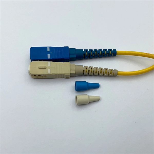
The goal is to fuse the two fibers together in such a way that light passing through the fibers is not scattered or reflected back by the splice, and so that the splice and the region surrounding it are almost as strong as the intact fiber. Fusion splicing is the process of fusing or welding two fibers together usually by an electric arc. Fusion splicing is the most widely used method of splicing as it provides for the lowest loss and least reflectance, as well as providing the strongest and most reliable joint between two fibers. Fiber Stripping: Selecting Precise Tools and Techniques Selecting the appropriate stripper will depend on the fiber coating diameter. This will typically be 250µm for bare fibers and 900µm for coated fibers. Reputable companies like Jonard, Fujikura, and INNO provide multi-hole strippers calibrated. Fiber misalignment and fiber geometry mismatch (e., core size, core-to-clad concentricity, core and cladding non-circularity, numerical aperture, etc. ) can result in real power loss across a splice joint. However, differences in the backscattering coefficients between two fibers can also show up. Fiber splicing means joining two optical fibers (permanently or temporarily) such that light guided in one fiber and reaching the joint (splice) can be transferred into the second fiber with low insertion loss.
[PDF]