The change of both physical length and strain-dependent refractive index of the fiber, are calculated by altering the bend radius of the sensor. The detection of the bend radius is determined by the shift of the Bragg wavelength from the reflection/transmission. Fiber Bragg grating (FBG) sensors have emerged as advanced tools for monitoring a wide range of physical parameters in various fields, including structural health, aerospace, biochemical, and environmental applications. This review provides a comprehensive overview of FBG sensor technology. A variation of the period of the grating inscripted in a fiber optic – induced by mechanical or thermal perturbation – causes a shift of the reflected peak wavelength, due to the related optical path length variation. where Pij are the Pockel coefficients of the elasto-optic tensor, n is the. Optical sensors based on Fiber Bragg Gratings (FBG) are becoming increasingly popular. They are easy to install, immune to electromagnetic interferences and can also be used in highly explosive atmospheres. But just how does a fiber Bragg grating work? Our experts answer this and other questions. In the field of mechanical engineering, the accurate calculation of bending strength for spur gears is fundamental to ensuring the reliability and durability of transmission systems. The basic approach involves simplifying the gear tooth as a cantilever beam and incorporating form factor and stress.
[PDF]
The normal recommendation for fiber optic cable is the minimum bend radius under tension during pulling is 20 times the diameter of the cable (d). While installers are aware of the fundamental importance of minimum bend radii, they often lack the practical know-how to systematically calculate bend radii under real installation conditions. Different fiber types, cable designs and load conditions each require specific bending radii calculations. This calculator helps you determine the minimum recommended bend radius for your fiber optic cable during installation and long-term use. Note: Some cables have. The calculator uses conservative routing multipliers, then compares the actual bend radius against the cable family minimum so you can spot risky turns early. Configuration type Cable family Installation phase Route style Route length (m) Used for bend density and overall planning context. Cable. To ensure optimal performance and long-term reliability, follow these industry-standard calculations: Copper Ethernet (Cat5e/Cat6/Cat6a): The standard rule of thumb is 4x the outer diameter of the cable. For shielded cables or thicker jackets, always consult the manufacturer's datasheet to prevent.
[PDF]
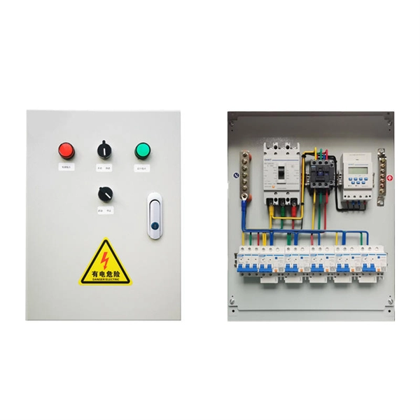
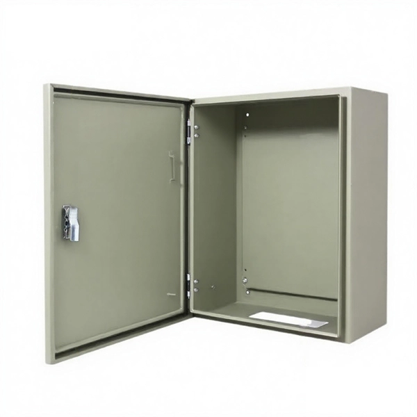
Reach inside panels, disconnects, and raceway to bend and position heavy duty cable with greater precision and less fatigue than bending by hand. The dies on the ends of these benders are sized to handle large wire gauges; fit your cable into the dies and push or pull the handle to bend. Smooth. Check each product page for other buying options. Need help? Online shopping for Tools & Home Improvement from a great selection of Wall Plates & Accessories, Breakers, Load Centers & Fuses, Electric Motors, Testers & more at everyday low prices. Start your sales inquiry online and an expert will connect with you. Easily find the nearest Schneider Electric distributor in your location. Find support resources for all your needs, in one place. Discover our range of products in Terminal blocks, protectors and. Buy a wholesale switchgear bending plate and experience smooth management and distribution of electricity. Mounting hardware is available as an add-on to any branch circuit power whip cable assembly. PDU Cables offers a variety of options that facilitate elevated mounting positions including beam and pedestal clamps, mounting bolts, brackets and mounting ears attached through the backs of boxes. NVent Hoffman BMP4080 Power Distribution Mounting Plate, Mild Steel, Use With Terminal Boxes, 14. 08 inches thick and is.
[PDF]
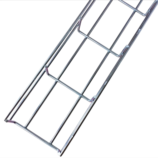
Here are the most common materials: Galvanized Steel – Provides high corrosion resistance and durability. Stainless Steel – Ideal for harsh environments with chemical exposure. Aluminum – Lightweight, rust-resistant, and easy to install. A cable tray system is defined as a system of raceways and associated fittings used to securely fasten or support cables. It's strong, durable, and can withstand a lot of wear and tear. There are two main types of steel used in cable tray manufacturing: mild steel and stainless steel. Mild steel is a cost - effective option for. Cable trays are mechanical support systems that provide a rigid structural system for electrical cables, raceways, and insulated conductors used for electric power distribution, control, signal instrumentation, and communication. When properly selected and installed, cable trays simplify routing, improve accessibility, and support future expansion while. Cable trays are designed to accommodate all types of electric wiring, providing a clean and accessible route for complex cable infrastructure. This guide will help you choose the best cable tray.
[PDF]

The typical specification range of return loss of a fiber connector is -15 dB to -60 dB. Return loss is also known as reflection loss. It indicates the amount of signal reflected back to the transmitting end. Return loss refers to the power loss caused by the reflection of part of the signal back to the signal source during transmission due to the discontinuity of the transmission. Insertion loss, also known as attenuation, is the loss of optical power that occurs when light passes through a fiber optic connector. It is caused by factors such as misalignment, air gaps, and imperfections in the connector components. The lower the insertion loss, the better the performance of. Reflectance (which has also been called "back reflection" or optical return loss) of a connection is the amount of light that is reflected back up the fiber toward the source by light reflections off the interface of the polished end surface of the mated connectors and air. It is also called. Insertion Loss (IL) is the amount of optical power lost as the signal travels from one point to another in a fiber optic link, usually across connectors or splices. Formula for. In optical fiber communication, insertion loss and return loss are two important parameters to evaluate the quality of interfaces between some optical fiber components, such as optical fiber connector, fiber patch cable, pigtail fiber, etc. While it's natural to have.
[PDF]

The max insertion loss of a fiber patch cable is 0. 75 dB (the maximum acceptable value) in the TIA standard. Insertion loss (IL) and return loss (RL) are key performance indicators of fiber optic patch cords. This article explains their concepts, standards, testing methods, and FiberMania's quality assurance workflow to ensure optimal network performance. Fiber optic patch cords are crucial components in. A: Fiber optic loss refers to the reduction in signal strength as it travels through the fiber optic cable. This can be due to various factors, including attenuation, connectors, and splices. Q: How is fiber optic loss measured? A: Fiber optic loss is typically measured using an Optical Loss Test. The estimate, called a "loss budget" is calculated using typical component losses for each part of the cable plant - the fiber, splices and/or connectors. If the measured loss exceed the calculated loss by a significant amount (remembering the inherent uncertainty in all measurements), the system. Insertion loss is usually shortened to IL, and the unit of measurement for insertion loss is dBm. ) in transmission systems. It is the power attenuation of the signal after. At TARLUZ, we specialize in manufacturing high-performance fiber optic patch cords that comply with global industry standards, ensuring optimal signal integrity and long-term stability.
[PDF]
The normal recommendation for fiber optic cable is the minimum bend radius under tension during pulling is 20 times the diameter of the cable (d). This includes pulling tension, minimum bend radius or diameter and crush loads. Installers must understand these specifications and know how to install cables without. Fiber optic cable bend radius is a critical mechanical parameter that determines how sharply a cable can be bent without risking microbending, macrobending, signal loss, or long-term structural fatigue. It is measured from the inside of the bend, not the outer curve. Fiber optic cables transmit data through light propagation within a glass core. The correct bend radius calculation is a fundamental prerequisite for high-quality fiber optic installations and is decisive for long-term network performance and reliability. While installers are aware of the fundamental importance of minimum bend radii, they often lack the practical know-how to. The bend radius of fiber cables is critical for maintaining high performance and longevity. This overview explains key standards, installation best practices, and consequences of exceeding limits during handling, routing, and management. What Is Bend Radius? You need to understand the concept.
[PDF]