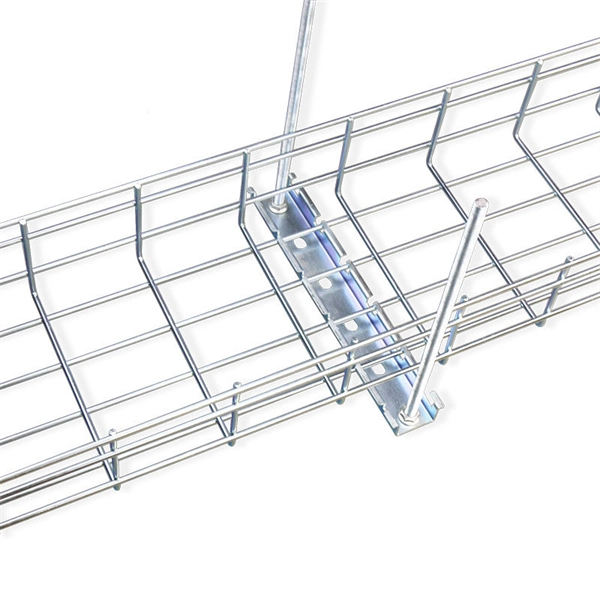
Cable Trays* — Max two 24 in. (610 mm) wide by max 6 in. (151 mm) deep open-ladder cable tray with channel-shaped side rails formed of 0. 54 mm) thick aluminum or min 0. In practice, cable tray dimensions are a system of interrelated measurements —width, depth, length, and material thickness—that directly affect cable fill compliance, heat dissipation, structural loading, and long-term expandability. From an engineering standpoint, cable tray dimensions are not. Perforated Cable Tray System expertly constructed from high-grade stainless steel, offering exceptional durability and resistance to corrosion. With side height 100mm. A properly designed and installed cable tray system will provide. Studs — Wall framing to consist of wood studs or channel shaped steel studs. Wood studs to consist of nom 2 by 4 in. Additional studs shall be used to completely frame. Best Size: Here, deep trays (75mm to 150mm) are used since power cables are typically thick and heavy. Data cables, such as your Wi-Fi or computer ones, are extremely sensitive. They do not get hot; however, they do not like to hang or sag. In case a data cable folds in an excessive manner, the. ect the minimum bend ra-dius for cables as they exit the bottom of the cable tray. A rung spacing of 6 to 9 inches (150 to 230 mm) is preferable when the cable tray cont d for instrumentation and control applications that require additional protec eferred to support and protect numerous small.
[PDF]

An Optical Splitter, also known as a beam splitter, is a passive optical device that divides a single input optical signal into two or more output signals. Conversely, it can also combine multiple signals into one. Knowing the difference between a splitter and an optical coupler helps you build better networks. You make your network work better when you pick the right device for each job. You can connect many users to one port with 1:n or 2:n splitters. By dividing a single optical signal from a central Optical Line Terminal (OLT) into multiple outputs for Optical Network Terminals (ONTs) at users' homes, splitters eliminate the need for dedicated fibers to each residence—slashing infrastructure costs while scaling network reach. This guide. In a Passive Optical Network (PON), a single optical fiber carries massive amounts of data using light. Signal Input: The fiber splitter receives the optical signal from the upstream network node and enters the splitter through the input fiber. Signal Distribution: Inside the splitter, according to the design structure and different. Splitters are passive optical devices that divide or combine optical signals, and they come in various types, including power splitters, uneven splitters, and wavelength-division multiplexing (WDM) splitters. Each type serves specific applications, enabling efficient use of optical infrastructure.
[PDF]

A ladder type cable tray tee is a fitting used to create a branch in a cable tray system, allowing cables to be routed in three directions. Its "T" shape provides a secure and efficient way to split cables from a main tray into two separate paths, ensuring organized and flexible. A cable tray tee and tee cover are components used in cable management systems to support and protect electrical and data cables. Here's a brief explanation of each:. Rigid steel cable tray tee fitting with zero tangent, safety bottom, and full accessory support. ventilation to heat producing cable such as power communication and other with the same or different width of the cable run. All fittings are available in sizes and types corresponding to the straight cable tray sections. These fitting are including: elbow, horizontal cross, vertical inside. NOTE : Equal or un equal tees can be supplied. When ordering state widths W1xW2xW3.. Office: 147/22 Nguyen Sy Sach Street, 15 Ward, Tân Binh Dist, HCMC,VN. Is it possible to connect 2 cabletrays with a "branch piece (left picture)" instead of a "tee (right picture)". The tee has 3 connectors, the branch piece only has 1 connector. I would like to ajust the "Type properties -> Fittings -> Tee" with the branch family, but can't get it accomplished.
[PDF]
Single mode and multimode fiber optic cables are two different types of fiber optic cable aimed at different use cases. Single mode cables are typically made with a single strand of glass at their core, leading to a n.
[PDF]
Bogdan Sirbu: One example I can think of is the H2020 L3MATRIXproject. On this project, we developed a 2D matrix of 64 different transceiver and receiver cells, achieving high radix and getting an extend.
[PDF]
Rodent damage in underground or aerial installations. Symptoms: Gradual performance decline over months/years. UV exposure degrading jacket materials. Use Case: Identifying macrobends, breaks, or sharp bends in. In the high-stakes world of optical networking, even a minor disruption in a Pigtail Fiber connection can cascade into costly downtime, affecting data centers, telecom services, or industrial systems. This article equips engineers and network operators with actionable strategies to diagnose. Fiber pigtail failures can lead to unexpected signal loss, link instability, and repeated maintenance. Understanding how to identify early warning signs can help reduce downtime and protect your network from unnecessary failures. A visual check is often the first step when diagnosing a defective. However, when signal loss occurs in a 12 fiber pigtail, it can lead to disruptions in network performance, such as decreased data transfer speeds, increased error rates, or even complete outages. Understanding the potential causes of signal loss and implementing effective troubleshooting methods is. Executive Summary: A fiber optic pigtail is one of the most commonly specified yet least understood components in structured cabling. Dust or oil contamination leads to signal loss. Always clean fibers before splicing. Using the wrong connector (LC vs SC) can cause compatibility.
[PDF]

Learn how to splice fiber optic cable using fusion splicing with this complete step-by-step guide. Includes tools, best practices, loss standards (ITU-T G. 652), cost analysis, and FAQs for network engineers and installers. 5,398 fiber splicing stock photos, vectors, and illustrations are available royalty-free for download. Template technician Fiberoptic Fusion Splicing. Worker connecting for Cable Internet signal and Wire connection with Fiber Optic Fusion Splicing machine,fiber optic cable splice machine in work. Splicing fiber optic cable is an extremely important phase for making dependable, high-speed communication infrastructures. Regardless of the type of fiber network you're deploying, be it for telecom, enterprise data centers, or smart city infrastructure, fusion splicing provides the benefits of. In this guide, we cover the basics of fiber optic splicing, how to perform splicing using two different methods, and finally some best practices to perform good fiber splicing. Ensure Your Splicing Tools are Clean – #2. For network managers and technicians, a poor splice can lead to significant signal degradation, network downtime, and costly troubleshooting. At Turn-Key. 🔧 Watch a real-time fiber optic splicing demo in action! In this step-by-step tutorial, learn how to splice fiber optic cables like a pro — perfect for telecom technicians, network engineers, and field techs.
[PDF]
The Fibre Channel physical layer is based on serial connections that use fiber optics to copper between corresponding pluggable modules. The modules may have a single lane, dual lanes or quad lanes that correspond to the SFP, SFP-DD and QSFP form factors. Fibre Channel does not use 8- or 16-lane modules (like CFP8, QSFP-DD, or COBO used in 400GbE) and there are no plans to use these expensive and comple.
[PDF]
When deploying fiber optics in the field, telecommunications companies need ways to safely and efficiently store and terminate cables. As many technicians know, having the right fiber optic patch and splic.
[PDF]