If the LOS light on your fiber router or ONT is blinking red, it usually means Loss Of Signal. This guide explains the likely causes, the checks you can do at home, and when the issue needs technician support. The LOS light on your router indicates the status of your internet connection to the Internet Service Provider (ISP). When it's green and steady, everything is fine. However, when it blinks red or stays solid red, it signifies a Loss of Signal, a problem preventing your router from communicating. A red light on your router can be a source of frustration and confusion. Fortunately, diagnosing and resolving these issues doesn't have to be complicated. Before you panic or call tech support, there are several simple fixes you can try at home that often solve this problem in minutes. Here are some steps you can take. You might feel like you're staring into the abyss of digital darkness, wondering what went wrong. But don't despair! This guide will walk you through the most common causes of router.
[PDF]

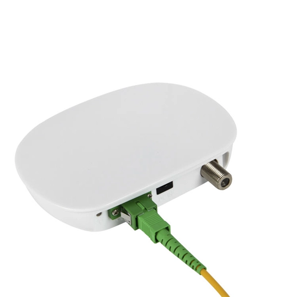
The first thing you should do is locate the fiber optic cable that comes from the service provider. Once inserted, make sure it is. However, setting up a fiber optic connection to your router can seem daunting if you're unfamiliar with the process. This comprehensive guide combines industry standards with field-tested practices to ensure you achieve a rock-solid. Setting up a fiber internet connection requires understanding key hardware components and following a specific connection sequence to establish your home network. This guide details the necessary physical and digital steps to connect your fiber line and activate your internet service. The technician powers, tests, and activates the connection to confirm full speed and signal quality. * In some instances, the ONT and the router are all in the same device, generally called a combo unit. Here's a step-by-step guide to help you through it. Understand the Basics Before diving in, familiarize yourself with the components involved:. Tecnobits - Router - How to connect a fiber optic cable to the router Hello, Tecnobits! 👋 Connecting fiber optic cables to the router so that your internet flies like a spaceship! 😉 Explore with us on our website! And don't miss our latest news. See you soon! 🚀 How to connect a fiber optic.
[PDF]
A distribution box serves as a central point for managing and distributing fiber optic cables. This device ensures reliable and efficient connectivity between various network components. By combining factory-installed connectors with spliced bare fiber, pigtails ensure that network installers can create fast, reliable, and cost-effective terminations. Without pigtails. A fiber pigtail is a type of fiber optic cable with a factory pre-terminated connector on one end and exposed fiber on the other. This design makes the fiber pigtail suitable for field termination using a mechanical or fusion splicer, playing a crucial role in the fiber optic cable installation. A Fiber Optic Termination Box is a small enclosure located at the terminal end of the fiber where it enters your customer premises. Its function is primarily to splice, secure, and protect the optical fibers connecting the incoming drop cable to the pigtail or patch cable. The connector end plugs into devices like transceivers or patch panels, while the bare end is typically fusion spliced to a fiber optic cable. You can splice the bare end with a fiber core of an optical cable, thus providing a connection for the fiber.
[PDF]
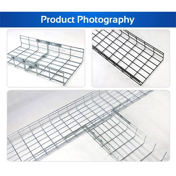
Optical cable tray is a system designed to protect and route fiber optic patch cords, cable assemblies to and from network cabinets, ODF and other terminal devices. Ducting offers ideal solutions for optical raceway requirements and application with pleasing appearance and easy. Our Fiber Cable Tray System is a comprehensive raceway solution for data center, enterprise, central office, and mobile switching center applications. Designed to route and protect fiber optic and high-performance copper cabling to and from network cabinets, distribution frames, and other terminal. Cable trays are a foundational part of this infrastructure, offering a secure, scalable, and organized method of managing fiber routing across diverse environments.
[PDF]

In short length cables a visual fault locator (VFL) can find where the cut is or find the bad connector at patch panels. For longer distance cables, the use of an OTDR is required. Once the fault is located, fusion splicers and splice-on connectors can be used to complete the repair. Fiber optic cables are the backbone of modern networks, delivering fast and reliable data transmission. Accidental cuts, breaks, or other damage can disrupt your network and cause costly downtime. With the right tools and techniques, you can efficiently repair damaged fiber cables and restore. Fiber optics offers advantages like EMI immunity and low attenuation (0. 2 dB/km), but it's fragile—susceptible to breaks, bends, and contamination. Repairs focus on restoring the light path with minimal signal loss (<0. A fusion. Visual inspection and specialized tools like OTDRs, OPMs, and VFLs are essential for identifying and locating physical damage or faults in fiber optic cables. Emergency restoration planning involves implementing backup power solutions, network redundancy planning, and strategies for prompt. Fiber optic cables are critical components of modern communication networks, transmitting vast amounts of data at lightning speeds.
[PDF]
This is a list of terrestrial fibre optic cable projects in Africa. While submarine communications cables are used to connect countries and continents to the Internet, terrestrial fibre optic cables are used to extend this connectivity to landlocked countries or to urban centers within a country that has submarine cable access. In most of the world, a large number of such cables exist, often a. NotesThis list was initially developed as part of AfTerFibre, a project to map terrestrial fibre optic cable projects in Africa. • • • •.
[PDF]
They can weigh between 60 to 200 kg per kilometer (39. 7 to 132 pounds per 1000 feet), depending on the design and materials used. The weight of fiber optic cables can vary widely based on the factors mentioned above. However, some general guidelines can provide a rough estimate: Indoor Fiber Optic Cables: These are typically lighter as they require less protection. Indoor cables can weigh anywhere from 10 to 30 kg per. Fiber per Tube *: No of tube(13-24) shall be with black tracer but black* tube(20) with white tracer. Fiber per Tube *: Tube identification with one black stripe. In case of Black tube with white marking. This cable is perfect for headend termination to a fiber backbone, termination of fiber rack systems, multi-floor deployment where select fibers are used at each floor, or intra-building backbones. It is suitable for all indoor applications where fiber optic cabling is needed. Lighter materials reduce overall cable weight 3. Strength and. CommScope all dry outside plant stranded loose tube cables deliver the same proven quality and performance offered in all CommScope cabling solutions. The construction features the use of dry. The Cisco ® family of QSFP-DD modules provide the industry's highest bandwidth density while leveraging the backward compatibility to lower-speed QSFP pluggable modules and cables. The Cisco 400GBASE Quad Small Form-Factor Pluggable Double Density (QSFP-DD) portfolio offers customers a wide variety.
[PDF]
This guide provides a comprehensive engineering perspective on ODFs—beyond the basic “what is an ODF” explanation—covering structural design, fiber management, MPO/MTP integration, and selection criteria for modern high-density deployments. Why ODFs are the Foundation of. This complete guide explores everything you need to know about ODFs — from their structure, types, and key components, to installation best practices and modern design trends. Whether you're building a central office, data center, or FTTx distribution network, understanding the right ODF. In the complex architecture of fiber optic networks, the Optical Distribution Frame (ODF) serves as the linchpin for organizing, protecting, and distributing optical signals. As data centers, enterprises, telecom operators, and smart-building infrastructures deploy increasingly dense fiber links, ODFs provide the structured. An ODF is a central hub in fiber optic networks, crucial for managing and organizing the variety of fiber-optic cables and connections entering a facility such as a telco central office (CO). They provide efficient fiber optic management, connectivity, and protection. What is Optical Distribution Frame An Optical Distribution Frame (ODF) is the central hub of your fiber optic network.
[PDF]

In this post, we'll walk you through practical tips, essential tools, common pitfalls, and the techniques that will help you get your fibre patch cable installations right the first time. Correct patch-cord installation is essential for maintaining low insertion loss, stable return loss, and long-term reliability in both indoor and outdoor fiber networks. Proper handling, routing, cleaning, bend-radius management, and connector alignment ensure that the optical link meets design. Proper connection of fiber optic cables is essential to harness these benefits fully, as even minor errors can lead to significant performance issues like signal loss. This guide addresses expert-certified best practices applied by professionals in the telecommunications, data. Yingda outlines the tools and materials needed to install fiber optic patch cords, as well as a complete step-by-step installation guide and important safety considerations to take. We will also tie this procedure back to the earlier discussion of multi-mode fiber types (OM1 to OM5) and connection. The Flex-Angle boot is designed to bend any angle or direction from straight to 90°. OMC flex angle boots for LC&SC fiber optic connectors are available on any single-mode or multimode patch cord. They are designed so the installer can pre-bend the boot into any direction or angle. Selecting the correct fibre patch lead is crucial for optimising signal performance and.
[PDF]

The Trans-Saharan Fibre Optic Backbone project will connect Chad to coastal countries via Niger, improving network resilience and undersea cable access. Chad has about 100 km of fibre left to install to complete its section of this backbone, slated for completion by the end of the. The Chadian government is seeking changes to an agreement with telecom operators SOTEL and Airtel as it moves to restart work on the N'Djamena–Mberé fiber-optic route, a link seen as vital to the country's digital connectivity. The companies signed a memorandum of understanding in April 2025, but. Africa's digital transformation is accelerating, but for landlocked nations, access to international internet capacity remains a critical challenge. On June 18, 2025, Chad and Niger began discussions to establish a fiber optic interconnection under the Trans-Saharan Fiber Optic Backbone (TSR). Chad's government has ordered major telecom operators Airtel and Moov Africa to connect to the national fibre-optic network within one week. This audacious. Officials in Chad are stepping up efforts to connect the central African state to a regional fiber-optic network after cable breakages caused by flooding in neighboring Cameroon caused a protracted internet blackout. Authorities in the country have been unable to reestablish internet. Chad's Minister of Posts and Digital Economy, Dr. Boukar Michel, has given the country's telecoms operators Airtel and Moov Africa one.
[PDF]

Plug an SEL-2810 Fiber-Optic Transceiver With IRIG-B directly into a standard 9-pin serial connector (DB-9). No special mounting is required. The SEL-2810 receives power from the host device via the connector; no separate power supply or power wiring is needed. It also requires no. Improve safety, signal integrity, and reliability by using optical fiber instead of wire for instrumentation, protection, automation and other applications that benefit from economical fiber-optic links up to ½ kilometer long. Fiber-Optic Link— Establish EIA-232 communication between devices over a. The RLH Contact Closure Fiber optic converter transmits 8 digital input signals over fiber optic cable. Applications include alarm event triggering, building automation, environmental control systems, fire & alarm systems, gate control, traffic signal control equipment, and more. Use two optical fibers instead of 32 wires between outdoor or remote equipment and the control building to reduce costs, improve safety, and boost reliability. SFP transceivers bridge electrical and optical signals, making them indispensable in data centers, telecom networks, and.
[PDF]

A8: Yes, multimode fiber optic cable can support high-speed data transmission depending on the fiber type and network equipment used. Multimode fiber (MMF) is an optical fiber designed to carry multiple light propagation paths—or modes—simultaneously. This is made possible by its relatively large core diameter, typically 50 or 62. 5 microns, compared to the ~9-micron core in single-mode fiber. The wider core accepts light from. Multi-mode optical fiber is a type of optical fiber mostly used for communication over short distances, such as within a building or on a campus. Multi-mode links can be used for data rates up to 800 Gbit/s. Multi-mode fiber has a fairly large core diameter that enables multiple light modes to be. In the realm of telecommunications and networking, multimode fiber optic cable plays a crucial role in efficiently transmitting data over short to medium distances. This guide aims to provide a concise understanding of multimode fiber optic cable and its applications. These fiber cables are structurally designed to transmit several light signals simultaneously, each of which is directed. Unlike copper cables, which rely on electrical signals, fiber optics use pulses of light to transmit data—offering unmatched bandwidth, low interference, and long-distance capabilities. But not all fiber cables are created equal: multimode (MM) and single mode (SM) fibers are the two primary types.
[PDF]
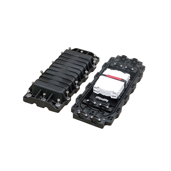
A fiber optic termination box is an enclosure designed to terminate incoming optical fiber cables and distribute optical signals to drop cables or patch cords. It integrates fiber splicing, adapter management, and cable protection in one compact unit. It is widely deployed in FTTH, FTTB, and other access networks to ensure stable signal transmission from backbone cables to end. ■ What is a Fiber Access Terminal (FAT)? A Fiber Access Terminal (FAT), also known as a Fiber Access Terminal Box (ATB) or Fiber Distribution Terminal (FDT), is a key component found in optimized fiber optic access networks for FTTH implementations. It acts like the "central nervous system". Fiber termination boxes play a vital role in ensuring efficient and reliable fiber management in FTTH applications. By understanding the components, types, and differences between various fiber management devices, businesses can make informed decisions when deploying and maintaining their fiber. But what exactly is the purpose of a fiber optic terminal box, and why is it so crucial in the realm of optical communication? First and foremost, a fiber optic terminal box serves as a robust protective shield for fiber optic cables and their delicate connections. It offers higher reliability and more flexible deployment and configuration than traditional terminal boxes. It is usually installed on the wall in the user's room or on the rack in the telecom room, and.
[PDF]
In conclusion, choosing the right fiber optic connectors is an important decision that can have a significant impact on the performance and reliability of your fiber optic network. By considering the various factors.
[PDF]

Configurations of 1x1 to n x m (e., 1x8 or 2x2) are available. The insertion loss of MM switches typically amounts to approximately 0. These switches can be delivered with any of the. Multimode fiber optic switches have emerged as a crucial component, enabling seamless connectivity and efficient data transmission. The MCSW Series Multicast Fiber Optical Switches enable simultaneous connection of one input to all outputs without loss. They support fully non-blocking, conflict-free switching of any number of optical inputs to any outputs, with complete configuration flexibility. The system is entirely passive. The Siemens Scalance X204-2 Multimode Switch requires a 24V UL Listed for Fire Application, Power Limited - Regulated Power Supply. Its Input Voltage is Regulated 24VDC and its Input Current is 265mA @ 24VDC. It is powered from the battery backed up local 24V power supply. Was this helpful? Does. For extremely precise measurement systems and sensor applications as well as for telecommunication applications LASER COMPONENTS offers fiber optical multimode (MM) switches with a fiber core diameter of 50 µm to 600 µm. There are switches are for all different kinds of requirements. Configurations. CONFIGURING THE SWITCH IN DESIGO CC/CERBERUS DMS. CYBERSECURITY DISCLAIMER.
[PDF]