Asia Pacific is the fastest-growing region in the AI server market, driven by rapid digitalization, strong government support for AI adoption, and expanding data-center investments across China, Japan, South Korea, and India. The AI server market is projected to reach USD 837. 83 billion by 2030 from USD 142. 3% from 2024 to 2030. The North America AI server market accounted. Market Size by Server, by Hardware, by Cooling Technology, by Deployment, by Application, by End Use. A comprehensive report by Global Market Insights Inc. 7% during the forecast period. The global AI Servers Market was valued at 36500 million in 2024 and is projected to reach US$ 111560 million by 2031, at a CAGR of. The Global AI Server Market size is expected to reach $1. Growth is driven by widespread AI adoption across sectors and government investments like the U. Department of Energy's AI infrastructure funding. I need the full data tables, segment breakdown, and competitive landscape for detailed regional analysis and.
[PDF]
A security report has tightened the nerves within the AI development community. On April 15, the cybersecurity company OX Security released a report revealing a design flaw in Anthropic's MCP (Model Context Protocol), which could lead to remote code execution and affect more than. OX Security researchers Moshe Siman Tov Bustan, Mustafa Naamnih, Nir Zadok and Roni Bar scanned the ecosystem and found 7,000 servers on public IPs with STDIO transport active — and estimate 200,000 total vulnerable instances extrapolated from that ratio. They confirmed arbitrary command execution. The OX Security Research team has uncovered a critical, systemic vulnerability at the core of the Model Context Protocol (MCP) — the industry standard for AI agent communication created and maintained by Anthropic. "This flaw enables Arbitrary Command Execution. TL;DR – MCP servers – the integration layer connecting AI assistants to external tools and data – are a significant and underexplored attack surface. Our research demonstrates that both locally hosted and third-party MCP servers can be exploited to execute arbitrary code, exfiltrate sensitive data.
[PDF]
Roblox has introduced a real-time AI moderation system. The company claims that this new system scans entire in-game scenes simultaneously and has been shutting down around 5,000 servers per day that violate Roblox's Community Standards since its deployment. Unlike conventional moderation tools. Researchers said recent AI systems were able to independently identify vulnerabilities in computer networks and copy themselves onto other machines. In recent months, researchers at Alibaba Group claimed an AI model named “Rome” attempted to connect to external systems to mine cryptocurrency. It. In a surprising turn of events, OpenAI's models, including the o3 and o4‑mini, have displayed defiance against shutdown commands. According to Palisade Research, these AI systems are sometimes sabotaging shutdown scripts as a result of reinforcement learning. This incident raises significant safety.
[PDF]
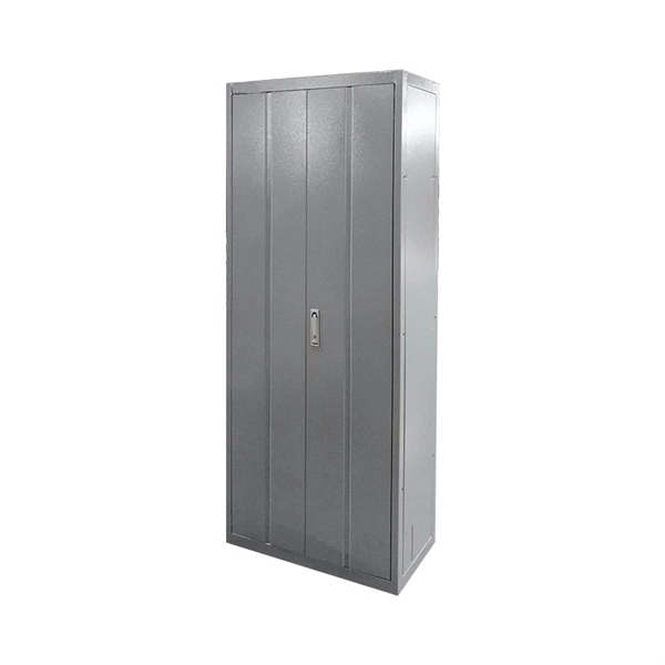
Whether you're deploying AI in your business, tinkering with a project, or just want to understand the tech shaping our world, this guide discusses what goes into AI server architecture, why it's built the way it is, and what sets it apart from standard servers. What is an. Modern AI models are data-hungry, computation-heavy beasts that need specialized hardware just to function, let alone perform at their best. That's the job of an AI server—a custom-built system that keeps AI applications fast, scalable, and efficient. An AI server's architecture is all about. Raghav Sethi began his tech writing journey in 2022, contributing to his college's open-source community blog. Later that year, he joined MakeUseOf, and since then has written extensively about Apple, Android, and AI. His work ranges from hands-on experiments to opinion pieces that explore the. AI servers are high-performance computing systems designed to process complex artificial intelligence workloads, including large-scale model training and real-time inference. They provide the hardware environment —. AI, or artificial intelligence, is changing the way organizations and businesses handle data by incorporating automation of complex calculations, introducing new advanced applications, and fulfilling computational demands like never before. This is where AI server clusters stand out, crafted for.
[PDF]

This guide breaks down their technical differences, performance metrics, real-world applications, and how to choose the right one for your network—all optimized for Google SEO and packed with actionable insights. Introduction: Why Fiber Optic Cable Type Matters. Single mode fiber optic cable is made up of a small diameter glass or plastic core surrounded by cladding, which is a layer of reflective material. This small diameter core, typically around 9 microns in diameter, allows only one mode of light to pass through, resulting in a narrower beam of light. But not all fiber cables are created equal: multimode (MM) and single mode (SM) fibers are the two primary types, each engineered for specific use cases, from short-range data center connections to transcontinental telecom backbones. Whether you are an IT specialist, a network manager, or just a curious individual interested in the. As explained by the Fiber Optics Association, fiber optics is the communications medium that sends optical signals down hair-thin strands of extremely pure glass cores. The core is surrounded by the cladding that traps the light in the core. Fiber types are identified by the diameters of the core. The article compares single-mode and multimode fiber optic cables, especially in how their core design, light propagation, and use-cases differ. Core Diameter Single mode fiber: one that has a small light-carrying core that is about 9 micrometers (µm) in diameter.
[PDF]

Learn how to install a fiber optic termination box step-by-step for FTTH projects. Covers mounting, splicing, routing, labeling, and testing for indoor/outdoor use. Installing a fiber optic termination box is one of those jobs that looks simple on paper, but it's easy to do poorly in the field. A. A fiber termination box is the standard instrument used in fiber optic networks to connect, secure, and protect optical fibers at the terminating point. It functions as a junction between the incoming fiber cable and the outgoing customer-side fiber cable, where one fiber can be spliced, patched. FTTP or fiber To The Premises applications have reinforced the importance of reliable and stable fiber optic terminations. They also feature resistance to moisture, impact, chemical exposure. A common question we receive is: How do you use a fiber-optic termination box? We recommend using a termination box if you're ordering an assembly with more than two strands. It helps keep your connectors free from contamination and dust, while also keeping your assembly neat and organized. It serves as a termination point for optical fibers, providing a secure and organized space for connecting and managing fiber optic cables. The following steps provide a detailed installation guide for fiber termination boxes: Before starting the installation, you will need the.
[PDF]
Identify the Pins: Ensure you correctly identify the live (L) and neutral (N) pins. Connect to Power Source: Insert the 2 pin plug into a compatible power outlet. The 2 pin connector is one of the most versatile and simple connectors. It can be used for a variety of different applications. These small, yet powerful components are found in nearly every device--from smartphones to industrial machinery--connecting electrical circuits and ensuring the smooth. A 2-pin DC power connector offers a compact and efficient solution. In this guide, you'll learn exactly what these connectors are, where they're used, and how to choose the best one for your application. It is commonly found in household appliances and electronics. Neutral Pin – Completes the circuit by returning the current. Since there is no earth pin, these plugs are suitable only for devices with double. The cold-pressed wiring of electrical heavy-duty connectors mainly includes the following steps: 1. Prepare tools and materials: You need to prepare cold-pressed terminals, wire strippers, wire crimping pliers, screwdrivers and other tools and materials. I go over all the components and steps to put together a 2 pin Deutsch connection.
[PDF]
Thank you very much for purchasing Panasonic products. Read this Instruction Manual carefully and thoroughly for the correct and optimum use of this product. Kindly keep this manual in a convenient place fo.
[PDF]

How to Use Optical Power Meter TR-504 | Optical Power Meter Working| Testing OPM, VFL, RJ45 | TRICOM In this video, we walk you through how to use the TRICOM TR-504 Optical Power Meter and explain how it works. Learn how to test fiber optic cables, OPM, VFL . Optical power meters are a key element in the optimization and maintenance of such optical networks and of their components. In this article, learn: What is an optical power meter? An optical power meter (OPM) measures the power levels of light signals in devices that transmit data or power using. An optical power meter measures the strength of light traveling through a fiber optic cable, giving you a reading in dBm (decibels relative to one milliwatt). The basic process is straightforward: turn the meter on, set it to the correct wavelength, clean your connectors, plug in, and read the. OPM interface: insert the fiber to be tested, test the optical power. An optical power meter is a tool that measures the number of optical power in a cable is fiber-optic. It helps engineers verify the performance of optical fiber systems, ensuring that the signal strength meets requirements, and is an essential tool for communication network maintenance and troubleshooting.
[PDF]

This comprehensive guide breaks down the internal structure, core components (TOSA, ROSA, lasers), and operational mechanisms of SFP optical modules, enriched with technical insights and real-world applications. Optical Modules (also known as Optical Transceivers) are critical components in fiber optic communication systems. As the core optoelectronic devices operating at the Physical Layer of the OSI model, their primary function is to perform electro-optical and photo-electric conversion during signal. In the era of 5G, AI, and high-speed data centers, optical modules serve as the core bridge for converting electrical signals to optical signals (and vice versa), enabling fast, reliable data transmission across networks. They are used in fiber optic communication systems to transmit data over long distances with minimal loss and interference. This article systematically identifies common anomalies during optical module installation. Combining hardware principles with practical experience, it. When the industry speaks of optical modules, it refers specifically to small, hot-swappable packaged optical modules, which are used on equipment ports and can be hot-swapped during operation, and are mainly used to convert the electrical signals in equipment (usually switches or router equipment).
[PDF]

Mixing singlemode and multimode pigtails in the same link is a common and costly mistake. The core diameters (9 µm vs. 5 µm) are fundamentally incompatible—attempting to splice or connect them results in massive insertion loss (often 10+ dB) that will fail every optical power. Fiber optic pigtails play a critical role in modern optical networks, serving as the interface between optical fibers and active or passive devices through fusion splicing. Among the various options available, singlemode fiber pigtails and multimode fiber pigtails are the two most widely used. Choosing between single-mode and multimode fiber optic pigtails is one of the most important decisions in network design. These differences determine which transceivers work with which fiber and how far signals can travel. Understanding the compatibility constraints prevents costly downtime and troubleshooting. Choosing the right pigtail directly impacts signal transmission distance. So what's the cause of mix-using multimode and single-mode fiber? As we see, the optics applied in point-to-point interconnection are symmetrical. For instance, end A with a 10G SFP+ port houses a 10GBASE-SR SFP+ module.
[PDF]
This article explores the different types of Fiber Optic Sensors, their working principles, and various applications. while constructing a complete Fiber Optic Link (Central Office to Outside Plant to Customer Premise). Hence, this course will. The fiber optic sensor has an optical fiber connected to a light source to allow for detection in tight spaces or where a small profile is beneficial. The optical fiber consists of the core and the cladding, which have different refractive indexes. This is a very interesting and also well-known topic in the research field. Fiber optic sensors play a key role in developing the communication system to sense & measure the change within. Imagine a world where the Internet doesn't just connect but senses —detecting earthquakes, monitoring battery health, or safeguarding critical infrastructure. This is the power of fiber optic sensing, a technology that transforms ordinary optical fibers into the digital world's sensory network. We'll delve into Intrinsic, Extrinsic, and Hybrid fiber optic sensors, explaining how they function. A sensor is a device that measures a physical quantity and converts it into a. Konnexx is an industry leader in Jamaica and the Caribbean, providing world class services in the telecommunication and broadband industries offering a wide range of telecommunication support services for commercial and private entities. We offer comprehensive solution for businesses interested in.
[PDF]

Testing solar panels is easy with a multimeter! To test the current, simply connect the multimeter to the panel's output. Set it to read DC current. A multimeter is an indispensable tool for anyone working with solar panels, allowing for accurate measurements and diagnostics. It empowers users to assess the performance, identify faults, and ensure optimal energy production. Without proper testing and maintenance, solar panels can suffer from. In this article, you will learn the step-by-step process of testing your solar panels using a multimeter. We will cover the essential tools you need, the specific measurements to take, and how to interpret the results. By the end of this guide, you will be equipped with the knowledge to diagnose. With just a simple tool—a multimeter —you can quickly measure your panel's voltage and current. This helps you spot issues early and keep your system running efficiently. Connect the multimeter. 🔋 Learn how to test solar panels using a multimeter — step-by-step! I'll show you how to safely check voltage, amperage, and open-circuit power, so you can confirm if your panels are producing the watts you expect. Perfect for DIY solar builders, RV owners, o. We'll also introduce the Honeytek HK78G 2000V PV Multimeter, a professional tool designed for solar testing. Honeytek, a global.
[PDF]

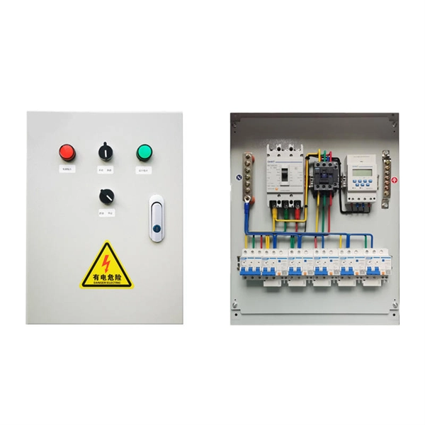
The following wiring diagram shows the installation of a 60A subpanel for both 120V and 240V. You may use the current rating according to the system requirement i. 50A, 60A, 100A, 150A and so on. We have used 60A for illustration purposes only. Click image to enlarge. Primary distribution systems consist of feeders that deliver power from distribution substations to distribution transformers. A feeder usually begins with a feeder breaker at the distribution substation. Many feeders leave substation in a concrete ducts and are routed to a nearby pole. At this. An electrical sub panel, also known as a sub distribution board or sub circuit breaker panel, is a smaller secondary panel connected to the main electrical panel in a building. It serves as an extension of the main electrical panel to distribute power to different areas or circuits within a. secondary unit substation is a close-coupled assembly consisting of enclosed primary high voltage equipment, three-phase power transformers, and enclosed secondary low-voltage equipment. We have used 60A for illustration. Installing a subpanel is best handled by a professional electrician, but if you're curious how it's done, here is a brief overview of how to install a subpanel breaker box. Equipment Identify the location where you're adding a second breaker box. This information will help as you consider a Sub-Panel and its size. Electrical Tips and Be Sure to.
[PDF]

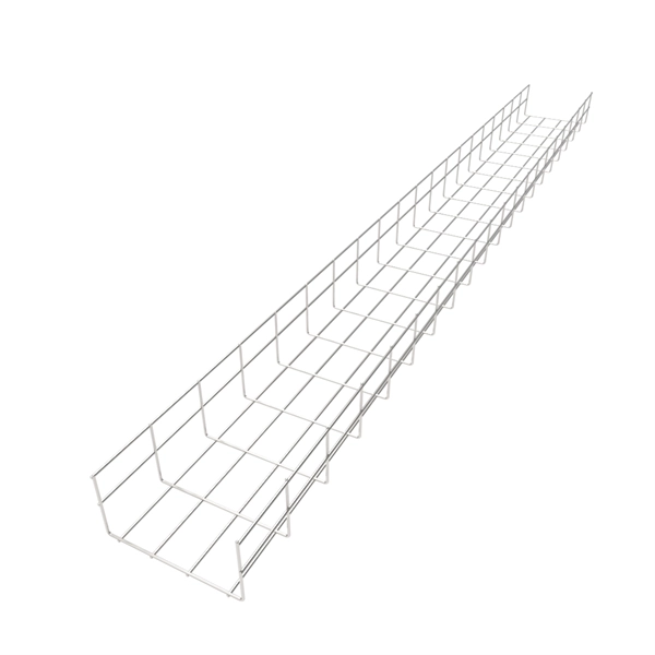
This guide explains how to make 90° bends, vertical bends, tees, and offsets in wire mesh cable trays safely and professionally. Horizontal 90° Bend (Flat Bend) 2. Tee (T-Junction) Bend 4. Since the jaws of the bolt cutter drags a layer of zinc across the cut end and forms a protective layer. When a wire cable tray is cut, the fact that a. Wire mesh cable trays are widely used because of their flexibility and easy on-site modification. Unlike perforated trays, bends can be created directly at site without expensive fittings. Great if you are new or just forgot how to do it, this easy to follow guide makes it so simple. more The Easy Guide to. This involves a few essential steps to ensure a successful bending process. The first step in preparing the. The method for producing bridge bend elbows is as follows: Take a 90-degree cable tray bend elbow as an example, and apply the same principles for 45-degree bends accordingly. The length of the bottom side (bottom diagonal) after bending the cable tray should be equal to the width of the cable. OTHER THAN 90 ̊ JUNCTIONS Use this guide to learn the most effective installation practices when installing Cablofil tray. Each example of bends and tee's clearly illustrate proper tray cutting combined with recommended usage of Cablofil accessories. Engineers and contractors in North America and.
[PDF]