
Beamsplitters are capable of dividing the incoming light into several streams. A number of factors impacts this splitting process; for example, the wavelength, intensity, or polarity, or the incoming light; or the construction and settings of the beamsplitter itself. 📦 For purchasing, use the RP Photonics Buyer's Guide for beam splitters. It provides an expert-curated supplier directory, buyer-focused technical background information, and structured selection criteria to support professional procurement decisions. What are Beam Splitters? A beam splitter (or. A beam splitter or beamsplitter is an optical device that splits a beam of light into a transmitted and a reflected beam. It is a crucial part of many optical experimental and measurement systems, such as interferometers, also finding widespread application in fibre optic telecommunications. The first surface is coated with an all-dielectric film having partial reflection properties over either the visible or the near-infrared spectrum. Beamsplitters are often classified according to their construction: cube or plate. Beam splitters are a fundamental element in optical systems. This division allows for the simultaneous analysis or utilization of the light's properties along two separate paths. The device is purely.
[PDF]
Fixed fiber optic attenuators are used to reduce the optical power signal in communication links. They work analogous to a step-down transformer. As the signal approaches a device or node in a communication link the power is reduced to a level that is suitable for its application. They are used to control the power level of optical signals at the outputs of light sources and electrical-to-optical (E/O) converters. Measured in decibels (dB), loss degrades signal quality, limits distance, increases bit-error rate, and escalates infrastructure cost. Understanding and managing it is critical to. The Fiber optic attenuator is an optical device that reduces the energy of the optical signal—used to attenuate the input optical power to avoid the distortion of the optical receiver due to the input optical power being too strong. It works by dissipating a portion of the optical power passing through it, thereby lowering the overall power level. Fiber optic attenuators.
[PDF]

A wiring diagram for a photocell and timeclock controller provides a step-by-step guide for installing and connecting all the components in a light system. It shows exactly how each component fits into the overall scheme of things, as well as what wires to use and which connections to. Intelligent Lighting Controls' wiring diagrams show detailed schematics of our solutions. A lighting control module is the “control center” for your lighting system. It acts as a bridge between your physical lighting fixtures and the smart systems that manage them. Instead of relying solely on traditional wall switches, you can control your lights via remotes, mobile or web apps. This guide will discuss the steps needed to integrate with URC Total Control. Commission CSI Controllers Step 2. Locate/Download latest TCM files/Module Step 3. Network Setup Step 6. Supports DALI V2 compatible switches and sensors, works out of the box. Simple and easy setup. ControlByWeb® IoT controllers are a great fit for lighting control in edge applications. Understanding the components that make up a modern lighting system, and how they relate to one another is key to ensuring the best performance and.
[PDF]

Its red laser shines through most yellow-jacketed optical fibers to help you pinpoint breaks, bends, faulty connectors, splices and other causes of signal loss. It has a reach of up to 5 km. The RPEN-210 is a necessity tool that should not be missing from any fiber plant manager or fiber optic installing technician. The Visual Fault Locator (VFL) Pen has a visible red light source centered on 650nm. Tool sends visible light over a fiber strand with a 10mW power, good enough to reach. The FLS-140 is the easiest way to identify optical fibers from end to end and locate polished connector endfaces. 5 dBm, but it couples approximately 3 dB less into a fiber. This is a Class 1 unit; the Class 1 limit is +3 dBm. The Class 1 limit (+3 dBm/2 mW) is intrinsically safe in all circumstances and is. This VFL has a fiber stub; its total emission is -1. 30 years of experience in R&D and manufacturing - Jilong JILONG launched the VFL-22M mini red light pen, pocket design, small and portable, integrated VFL/LED function, strong and stable light source, strong penetrating. A visible laser radiation source is one of the simplest devices and is designed to produce red light with a wavelength of 650 nm, which is transmitted through an optical fiber. The main purpose of this device is to locally detect various types of damage (such as breaks, bends, poor splicing, etc.
[PDF]
This article explores the different types of Fiber Optic Sensors, their working principles, and various applications. while constructing a complete Fiber Optic Link (Central Office to Outside Plant to Customer Premise). Hence, this course will. The fiber optic sensor has an optical fiber connected to a light source to allow for detection in tight spaces or where a small profile is beneficial. The optical fiber consists of the core and the cladding, which have different refractive indexes. This is a very interesting and also well-known topic in the research field. Fiber optic sensors play a key role in developing the communication system to sense & measure the change within. Imagine a world where the Internet doesn't just connect but senses —detecting earthquakes, monitoring battery health, or safeguarding critical infrastructure. This is the power of fiber optic sensing, a technology that transforms ordinary optical fibers into the digital world's sensory network. We'll delve into Intrinsic, Extrinsic, and Hybrid fiber optic sensors, explaining how they function. A sensor is a device that measures a physical quantity and converts it into a. Konnexx is an industry leader in Jamaica and the Caribbean, providing world class services in the telecommunication and broadband industries offering a wide range of telecommunication support services for commercial and private entities. We offer comprehensive solution for businesses interested in.
[PDF]

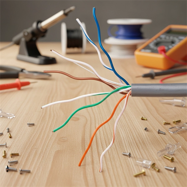
They are the bridge between fiber optic cables in the field and the equipment or patch panels that manage them. By combining factory-installed connectors with spliced bare fiber, pigtails ensure that network installers can create fast, reliable, and cost-effective terminations. Pigtail connections are most frequently used to ground a switch or electrical outlet and for electrical devices that need to connect to multiple circuit wires. A pigtail is composed of three strands of wire. We'll guide you through the fundamentals of creating secure links between multiple conductors and terminals. Pigtails act as bridges, allowing you to connect several wires to a single point without overloading connections. Professionals often prefer this method because it isolates issues. Fiber pigtails are simple in appearance, yet essential in function. It ensures a secure connection by combining wires with a wire connector, like a twist-on connector or a wire nut, and then linking them to the intended terminal or fixture. Pigtails serve. A pigtail wire is a short cable used to lengthen short wires. This pigtail technique is applicable in several home and automotive wiring projects, especially for circuit grounding wires. The National Electrical.
[PDF]
Part two of this series provides details on how to build the beam splitter. It is made from regular float glass without any coating. Watch part 1 if you want. This article explains how to create a beam splitter cube in Sequential Mode. One of the biggest challenges for modeling such a system is that multiple ray paths cannot be simultaneously traced in Sequential Mode. Thus, multiple configurations are needed to trace rays along both the transmitted and. Beamsplitters are optical components used to split incident light at a designated ratio into two separate beams. Additionally, beamsplitters can be used in reverse to combine two different beams into a single one. Method A: Diffraction Grating surface and multi-configuration 2. Development steps Inserting general parameters for simulation (wavelength, aperture,. It is a crucial part of many optical experimental and measurement systems, such as interferometers, also finding widespread application in fibre optic telecommunications. In its. T E3 + RE4, where T; R are the transmission and re ection coe cients for the beam splitter. Note that jT j2 is the transmitted intensity. Similarly, E2 ! RE3 + T E4. The transformation matrix is then given by The elements of the beam splitter transformation matrix B are determined using the.
[PDF]

Professional Cable Tray Elbow Making | Metal Fabrication Tutorial Learn how to make cable tray elbows professionally with step-by-step guidance. This video shows metal fabrication techniques, DIY cable tray projects, and tips for perfect bends and joints. Whether you are a DIY enthusiast. The method for producing bridge bend elbows is as follows: Take a 90-degree cable tray bend elbow as an example, and apply the same principles for 45-degree bends accordingly. The length of the bottom side (bottom diagonal) after bending the cable tray should be equal to the width of the cable. This manual is designed to guide workers through the detailed production process of ladder cable trays, including the manufacture of horizontal elbows, tees, crosses, reducing bends, and vertical bends, with emphasis on precision, safety, and quality control. What's Involved in Producing Ladder. The bends, tees, crosses, risers and reducers of wire mesh cable tray can be easily and quickly made live at the project by using a bolt cutter. Since the jaws of the bolt cutter drags a layer of zinc across the cut end and forms a protective layer. When a wire cable tray is cut, the fact that a. How to bend 22. 5 DEGREE OF CABLE TRAY 3 LA. How to bend 90 degree of cable tray 3 line with the same distance :// • HOW TO BEND 90 DEGREE OF CABLE TRAY 3 LINE. Enjoy the videos and music you love, upload original content, and share it all with friends, family, and the world on YouTube.
[PDF]
In general, foreign suppliers enter the Chilean market by appointing an agent, distributor, or wholesaler. Most are small-to-medium size firms. Several large firms handle different product lines and operate a.
[PDF]
Visible light communication (VLC) is an advanced, highly developed optical wireless communication (OWC) technology that can simultaneously provide lighting and high-speed wireless data transmission. A VLC system has several key advantages: ultra-high data rate, secure communication channels, and a. In some situations, visible light communication (VLC) has considerable advantages over the more generally utilized radio frequency (RF). This chapter delves into the fundamentals of VLC, beginning with an insightful exploration of its background and subsequently addressing the advantages and. Efficiency, durability and long life span of LEDs make them a promising residential lighting equipment as well as an alternative cheap and fast data transfer equipment. Appliance of visual light in data communication by means of LEDs has been densely searched in academia. In this paper, we explore. Visual light source of Lano Technology is designed to meet the demands of various industries, our visual light sources deliver exceptional brightness and clarity, ensuring optimal visibility for your applications. With a wide range of product models available, you can find the perfect solution for. Below find pdf documentation available for Visual Lighting. You can also view the Visual Lighting Manual in web help format. Visual is powerful lighting software engineered to bring.
[PDF]
Lighting Control System | Smart Lighting Wiring Setup | Full Guide In this video, you will learn how to connect and install a Lighting Control System step-by-step. This guide covers wiring setup, switch modules, dimming control, sensor setup and panel . as a guide for proper and reliable installation. The mounting location should e selected and prepared based on the application. All electrical wiring and mounting hardware (i. ) should be prepared with consideration of the requirements o cuit breaker before. Intelligent Lighting Controls' installation guides provide detailed instructions on how to install all of our solutions. The Lightolier Controls Optio Lighting Control Panels are high-performance, wall mounted lighting control panels which offer a wide range of dimming and relay modules to accommodate any lighting control application.
[PDF]

A beamsplitter is a common optical component that partially transmits and partially reflects an incident light beam, usually in unequal proportions. In addition to the task of dividing light, beamsplitters can be employed to recombine two separate light beams or images into a single. Beamsplitters are fundamental components in optical engineering, serving to precisely divide a single input beam of light into two distinct output beams. This division allows for the simultaneous analysis or utilization of the light's properties along two separate paths. It is a crucial part of many optical experimental and measurement systems, such as interferometers, also finding widespread application in fibre optic telecommunications. a laser beam) into two (or sometimes more) beams, which may or may not have the same optical power (radiant flux). Different types of beam splitters exist, as described in the. The beam splitter splits and then recombines infrared radiation, while the detector picks up the resulting signal. It's sensitive to both intensity and frequency. Together, they decide just how accurately an instrument captures those unique infrared “fingerprints” from different substances.
[PDF]

These splitters act as an interface between the microscope and the camera, emitted light from the sample passes from the microscope to the splitter, and are split based on wavelength before being projected onto sections of the camera sensor. In practice, the reflective layer absorbs some light. A beam splitter or beamsplitter is an optical device that splits a beam of light into a transmitted and a reflected beam. It is a crucial part of many optical experimental and measurement systems, such as interferometers, also finding widespread. Beamsplitters are optical components used to split incident light at a designated ratio into two separate beams. This division allows for the simultaneous analysis or utilization of the light's properties along two separate paths. If light incident direction and polarization conditions change, it may impact the ratio. Reflection properties change when light is projected onto the. The beam splitter splits and then recombines infrared radiation, while the detector picks up the resulting signal. It's sensitive to both intensity and frequency. Together, they decide just how accurately an instrument captures those unique infrared “fingerprints” from different substances.
[PDF]
Single-mode optical modules use LD (Laser Diode) or LEDs with a narrow spectral line as the light source. Single - mode optical modules are used for long - distance transmission, generally over 10km, and can reach. Signal Transmission: Single-mode fiber transmits light in a single path. This keeps signal loss and dispersion low for longer distances. Multi-mode fiber disperses light in multiple paths. I've seen people use a single-mode. In fiber-optic communication, a single-mode optical fiber, also known as fundamental- or mono-mode, is an optical fiber designed to carry only a single mode of light - the transverse mode. This article explores what single-mode fibers are, how they are designed, and their applications in various fields. It has a narrow core diameter of 8-10 microns and uses a laser or highly-focused light source to send light signals down the fiber.
[PDF]

This guide on how to fix router red light, will walk you through the common reasons behind the red light and provide step-by-step solutions to bring your router back online. A red light on your router can be a source of frustration and confusion. It often indicates that something is wrong with your internet connection or the device itself. Fortunately, diagnosing and resolving these issues doesn't have to be complicated. You might feel like you're staring into the abyss of digital darkness, wondering what went wrong. But don't despair! This guide will walk you through the most common causes of router. Experiencing a solid red broadband light on your router can be frustrating and indicates a disruption in your internet connection. Understanding the possible causes and fixes for this issue is crucial to getting your connection back on track. Here are some steps you can take. The following article will explain why the Internet is light red and what you need to do to fix it. What does it mean by Internet Light Red On Router? Our router's lights are.
[PDF]


