
In this video, we'll walk you through the process of wiring a home distribution box with a detailed connection diagram. This guide provides step-by-step instructions for connecting a distribution box and highlights key factors to consider during installation. What Is a Distribution Box? A distribution box, also known as an electrical distribution board, is a critical component in electrical systems. Whether you're an electrician or a DIY enthusiast, this guide will help you understand the basics of home electrical distribution. more Welcome to our channel! In this video. Correct wiring methods for circuit breakers within distribution boxes are fundamental to ensuring electrical safety and compliance with established codes. The distinction between 1P and 2P circuit breakers plays a pivotal role in determining the appropriate protection level for various circuits. Single phase DB box wiring involves connecting the live, neutral, and earth wires to their respective terminals in the distribution board. Wiring a single-phase distribution board (DB) box is a fundamental task for. A residential breaker box, or load center, is the heart of a home's electrical distribution system. This panel routes power from the utility service to every circuit while housing circuit breakers that provide overcurrent protection. Installing or replacing a load center is a complex task involving.
[PDF]
Run the loopback-detect untagged mac-address ffff-ffff-ffff command in the system view to broadcast BPDUs for loopback detection and prevent them from being terminated by unexpected devices. Huawei's comprehensive portfolio of products and solutions enables you to realize smooth digital transformation and rapid growth of virtualization, Big Data, and cloud services. Huawei switches already help customers achieve success in industries such as finance, Internet, retail, education. Plan the network configurations, configure loop prevention protocols, and enable loopback detection to prevent loops. They provide ultra-high-density 10GE/40GE/100GE/200GE/400GE full-rate access ports, meeting customers' requirements for quickly building campus networks with a simplified. CloudEngine S12700H series switches are Huawei's next-generation modular core/aggregation switches designed for high-end campus networks in the all-wireless era of Wi-Fi 6/7. CloudEngine S12700H series switches come in two models, which offer four and eight LPU slots, respectively. The S9700 uses an advanced multilayer switching architecture to support sustained bandwidth upgrading and to provide 40GE. This document provides campus networks typical configuration examples and feature typical configuration examples. "Campus Networks Typical Configuration Examples" provides typical campus network networking modes and a variety of deployment examples.
[PDF]

This list of bridges in Spain lists bridges of particular historical, scenic, architectural or engineering interest. Road and railway bridges, viaducts, aqueducts and footbridges are included. Roman, medieval or iron, the most spectacular bridges in Spain are very varied. They are, together with castles and fortresses, some of the best examples of civil engineering in the country. The oldest bridges were part of great roads and defended the passages to their cities. Location - Geographical Location of the Bridge. Autonomous Community - one of the 17 autonomous communities of Spain. Type - Type of bridge. Bridges bigger than 100m. 19?? ↑ "Puente sobre El Guadalquivir, su Puerta y la Calahorra, Córdoba". Alcántara Bridge The Alcántara Bridge is an ancient Roman bridge that is located in the town of the same name. The name “Alcántara” was derived from. Completed in 2005, this was the very first steel bridge to be built on the Spanish High-Speed Railway (HSR) network, belonging to the section between Barcelona and the French Border. The 574 m long bridge comprises two parts: a 307 m long steel–concrete structure crossing the busy highway AP-7 and. ???? ???? ???? The following 35 pages are in this category, out of 35 total.
[PDF]

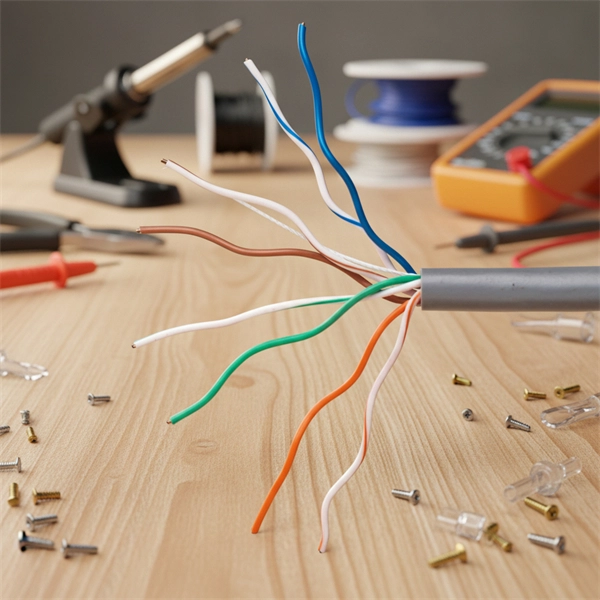
Cable Trays* — Max two 24 in. (610 mm) wide by max 6 in. (151 mm) deep open-ladder cable tray with channel-shaped side rails formed of 0. 54 mm) thick aluminum or min 0. In practice, cable tray dimensions are a system of interrelated measurements —width, depth, length, and material thickness—that directly affect cable fill compliance, heat dissipation, structural loading, and long-term expandability. From an engineering standpoint, cable tray dimensions are not. Perforated Cable Tray System expertly constructed from high-grade stainless steel, offering exceptional durability and resistance to corrosion. With side height 100mm. A properly designed and installed cable tray system will provide. Studs — Wall framing to consist of wood studs or channel shaped steel studs. Wood studs to consist of nom 2 by 4 in. Additional studs shall be used to completely frame. Best Size: Here, deep trays (75mm to 150mm) are used since power cables are typically thick and heavy. Data cables, such as your Wi-Fi or computer ones, are extremely sensitive. They do not get hot; however, they do not like to hang or sag. In case a data cable folds in an excessive manner, the. ect the minimum bend ra-dius for cables as they exit the bottom of the cable tray. A rung spacing of 6 to 9 inches (150 to 230 mm) is preferable when the cable tray cont d for instrumentation and control applications that require additional protec eferred to support and protect numerous small.
[PDF]

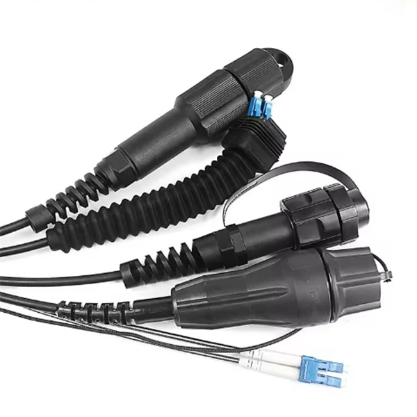
The core measurement procedure follows five steps: Turn on the meter and let it warm up. Most meters need a brief stabilization period before readings are reliable. Check your model's manual, but a minute or two is typical. Set the wavelength to match your light source. Fiber loss is the difference between the power when light is coupled from the transmitting end to the fiber and the power when the light reaches the receiving end. Generally speaking, when measuring the. An optical power meter measures the strength of light traveling through a fiber optic cable, giving you a reading in dBm (decibels relative to one milliwatt). The basic process is straightforward: turn the meter on, set it to the correct wavelength, clean your connectors, plug in, and read the. A power meter and light source are essential test tools that work in tandem to measure fiber optic cable loss and evaluate the quality of optical links. They provide the data necessary to quantify signal loss and pinpoint issues that could impact network performance. Here's how they work: A power. You measure optical power in dBm or insertion loss in dB. Verify light travels from transmitter to receiver. We'll give you the basic information you need and provide some printable references.
[PDF]

A wiring diagram for a photocell and timeclock controller provides a step-by-step guide for installing and connecting all the components in a light system. It shows exactly how each component fits into the overall scheme of things, as well as what wires to use and which connections to. Intelligent Lighting Controls' wiring diagrams show detailed schematics of our solutions. A lighting control module is the “control center” for your lighting system. It acts as a bridge between your physical lighting fixtures and the smart systems that manage them. Instead of relying solely on traditional wall switches, you can control your lights via remotes, mobile or web apps. This guide will discuss the steps needed to integrate with URC Total Control. Commission CSI Controllers Step 2. Locate/Download latest TCM files/Module Step 3. Network Setup Step 6. Supports DALI V2 compatible switches and sensors, works out of the box. Simple and easy setup. ControlByWeb® IoT controllers are a great fit for lighting control in edge applications. Understanding the components that make up a modern lighting system, and how they relate to one another is key to ensuring the best performance and.
[PDF]

A ladder type cable tray tee is a fitting used to create a branch in a cable tray system, allowing cables to be routed in three directions. Its "T" shape provides a secure and efficient way to split cables from a main tray into two separate paths, ensuring organized and flexible. A cable tray tee and tee cover are components used in cable management systems to support and protect electrical and data cables. Here's a brief explanation of each:. Rigid steel cable tray tee fitting with zero tangent, safety bottom, and full accessory support. ventilation to heat producing cable such as power communication and other with the same or different width of the cable run. All fittings are available in sizes and types corresponding to the straight cable tray sections. These fitting are including: elbow, horizontal cross, vertical inside. NOTE : Equal or un equal tees can be supplied. When ordering state widths W1xW2xW3.. Office: 147/22 Nguyen Sy Sach Street, 15 Ward, Tân Binh Dist, HCMC,VN. Is it possible to connect 2 cabletrays with a "branch piece (left picture)" instead of a "tee (right picture)". The tee has 3 connectors, the branch piece only has 1 connector. I would like to ajust the "Type properties -> Fittings -> Tee" with the branch family, but can't get it accomplished.
[PDF]
Visible light communication (VLC) is an advanced, highly developed optical wireless communication (OWC) technology that can simultaneously provide lighting and high-speed wireless data transmission. A VLC system has several key advantages: ultra-high data rate, secure communication channels, and a. In some situations, visible light communication (VLC) has considerable advantages over the more generally utilized radio frequency (RF). This chapter delves into the fundamentals of VLC, beginning with an insightful exploration of its background and subsequently addressing the advantages and. Efficiency, durability and long life span of LEDs make them a promising residential lighting equipment as well as an alternative cheap and fast data transfer equipment. Appliance of visual light in data communication by means of LEDs has been densely searched in academia. In this paper, we explore. Visual light source of Lano Technology is designed to meet the demands of various industries, our visual light sources deliver exceptional brightness and clarity, ensuring optimal visibility for your applications. With a wide range of product models available, you can find the perfect solution for. Below find pdf documentation available for Visual Lighting. You can also view the Visual Lighting Manual in web help format. Visual is powerful lighting software engineered to bring.
[PDF]
Solid Green: The ONT is powered on and functioning normally. What to check: Make sure the power cable is securely plugged into both the ONT and a working wall outlet. If you're using a power strip, check that it's turned on. Learn what each light on your fiber equipment means—from power and fiber signal to Ethernet and phone service—and how to quickly troubleshoot issues. This light shows whether your ONT is getting power. No Light: The ONT is not receiving. The Optical Network Terminal (ONT) is a crucial device in modern telecommunications, serving as the interface between your home network and the fiber-optic internet connection provided by your Internet Service Provider (ISP). The ONT has a series of lights that indicate its status and any potential issues. In this article, we will delve into. Power down for 15mins then power back on and wait 3mins for the lights to settle Power connector has come loose. Problem with the plug socket. Optical: This should be a solid green at all times (If the power light is off, this will also. This guide is designed to offer an explanation on how to troubleshoot issues with a CityFibre ONT (Optical Network Terminal). For more help topics, please visit the main Support Page. If you would like details on Freeola Broadband tariffs using the CityFibre Network, please visit our Broadband. You can use the status lights on your optical network terminal (ONT) to help find and fix internet issues. An ONT may also be called a Service box.
[PDF]
Lighting Control System | Smart Lighting Wiring Setup | Full Guide In this video, you will learn how to connect and install a Lighting Control System step-by-step. This guide covers wiring setup, switch modules, dimming control, sensor setup and panel . as a guide for proper and reliable installation. The mounting location should e selected and prepared based on the application. All electrical wiring and mounting hardware (i. ) should be prepared with consideration of the requirements o cuit breaker before. Intelligent Lighting Controls' installation guides provide detailed instructions on how to install all of our solutions. The Lightolier Controls Optio Lighting Control Panels are high-performance, wall mounted lighting control panels which offer a wide range of dimming and relay modules to accommodate any lighting control application.
[PDF]

This is the first and crucial connection—attach the incoming live wire (typically marked with brown or red insulation) to the main terminal in the distribution box. Before you begin installing a distribution box, make sure you have the right tools and materials. Below is a quick checklist of everything you will need for a safe and efficient installation: Connecting a distribution box involves several steps to ensure proper electrical flow. Follow this guide. Applications - The minimally invasive retrofit kit enables the opportunity existing remote power infrastructure cross arm, & wiring) providing the total cost of ownership. Failure to strictly adhere to the warnings and cautions as well as the installation instructions may result in serious personal. Hey, in this article we are going to see the Single Phase Distribution Box Wiring Diagram and Connection Procedure. Whether you're an electrician or a DIY enthusiast, this guide will help you understand the basics of home electrical distribution. What is Distribution Board? Distribution board. Power source through switch box - When power comes through a box containing a light switch and continues on to the light, the switch is attached on one terminal to the black (or sometimes red) line from the power source and on the other terminal to the black (or red) line going on to the light.
[PDF]

Average Optical Power: How bright the light is (measured in dBm). Too dim? Your signal gets lost in the fiber. Extinction Ratio: The difference between “on” (1) and “off” (0) light power. A higher ratio = cleaner signals. Transmitter Side: An electrical signal hits a laser diode (LD) or LED, which spits out light. Receiver Side: Light enters a photodetector (like a tiny solar cell), which turns it back into electricity. A built-in amplifier boosts the signal for your. The average transmitted optical power refers to the optical power output by the light source at the transmitting end of the optical module under normal working conditions, which can be understood as the intensity of light. In communication, we usually use dBm to represent optical power. However, in practical use, we adopt the average Tx power. The transmission power is related to the. This article provides an in-depth analysis of two key performance indicators of optical modules: transmitter power and receiver sensitivity. Transmitter power characterizes the average optical power output from the laser under rated conditions, while receiver sensitivity indicates the minimum. An optical module is a connecting module that serves as an optical-electrical conversion device. At the receiver end, the optical signals are reconverted into electrical.
[PDF]
In general, foreign suppliers enter the Chilean market by appointing an agent, distributor, or wholesaler. Most are small-to-medium size firms. Several large firms handle different product lines and operate a.
[PDF]

This guide on how to fix router red light, will walk you through the common reasons behind the red light and provide step-by-step solutions to bring your router back online. A red light on your router can be a source of frustration and confusion. It often indicates that something is wrong with your internet connection or the device itself. Fortunately, diagnosing and resolving these issues doesn't have to be complicated. You might feel like you're staring into the abyss of digital darkness, wondering what went wrong. But don't despair! This guide will walk you through the most common causes of router. Experiencing a solid red broadband light on your router can be frustrating and indicates a disruption in your internet connection. Understanding the possible causes and fixes for this issue is crucial to getting your connection back on track. Here are some steps you can take. The following article will explain why the Internet is light red and what you need to do to fix it. What does it mean by Internet Light Red On Router? Our router's lights are.
[PDF]

This guide will walk you through the process of checking photo sensors using a multimeter, covering various types of photo sensors, the necessary tools and safety precautions, and the specific measurement techniques involved. Knowing how to effectively use a multimeter to test photo sensors can save you time, money, and frustration when dealing with malfunctioning devices. more What is a Voltage Divider? | What is a Voltage. Before replacing the sensor or fixture, it's efficient testing it first, With a few tools and a step-by-step process you can find whether your outdoor lighting control system is working as intended or if the problem lies elsewhere. In this complete guide from Lead-Top, a global leader in photocell. In this blog post, we explain step-by-step how to troubleshoot a sensor with a digital multimeter (DMM). Here are the steps: Troubleshooting a sensor measurement failure requires mechanical tools to uncover the protective shields or components so you can reach the sensor in question. Always follow the manufacturer's instructions for the sensor and multimeter. Ensure the sensor is properly connected to the multimeter and. A multimeter is an indispensable diagnostic tool for anyone working with electronics, electrical systems, or indeed, sensors. It's a versatile device capable of measuring voltage, current, and resistance, providing crucial insights into the health and functionality of electrical circuits and.
[PDF]

