A cable tray is a structural system used to support insulated electrical cables used for power distribution, communication, and control. It provides a secure pathway that prevents cable damage, simplifies maintenance, and reduces the risk of overheating. Explore various cable tray types and sizes for electrical installations. Learn about ladder, perforated, solid-bottom, wire mesh, and channel trays in this complete guide. What is Cable Tray Systems? 1. Wire Mesh Cable Tray. When it comes to modern wiring systems, cable trays play an essential role in managing, protecting, and organizing cables. Whether you are setting up electrical wiring in an office, industrial plant, or even under a desk, choosing the right cable tray ensures safety, efficiency, and neatness. Unlike conduit systems, cable trays allow cables to be laid in bundles, improving accessibility, heat. Cable tray are essential components in electrical and telecommunications installations, providing a practical solution for cable tray management in both commercial and industrial environments. They are designed to accommodate and support multiple cables, providing a systematic approach to wiring.
[PDF]

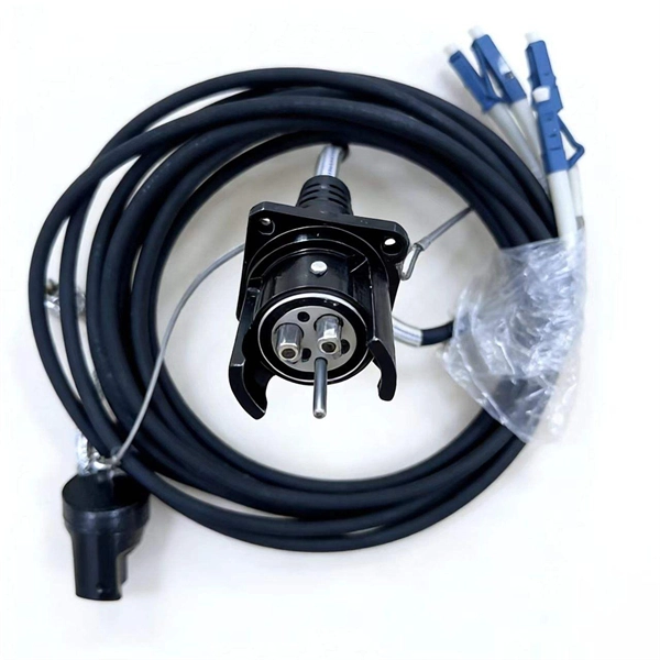
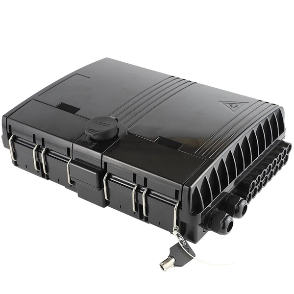
How to hardwire a Self-Regulating heat cable into a junction box, with a tutorial of the final end seal. First thing, get the sealing ring and connect it onto the connector body. Make sure it gets onto the very e. Safety comes first, and clear info makes it doable. Know Your. We'll show you how to size the heater, run a new, safe 240-volt circuit and install a programmable thermostat. Most homes have sufficient capacity for the new circuit in the service. If you're working with heating cables, understanding how to connect them safely and efficiently is crucial. In this guide, we'll break down the steps in simple terms. Whether you're a DIY enthusiast or a professional, this article is here to help. Stay safe and ensure proper installation with these. I need help wiring an electric furnace with heat elements. I ran number 6 wire with ground from my 100 amp service box where I installed a 60amp double pole breaker. The furnace comes with an other set of breakers one 60amp and one. A distribution board or distribution box is where the main power supply is distributed to multiple loads. Single Phase Distribution Box generally consists of Double Pole MCBs, Single Pole MCBs, and RCCBs.
[PDF]

Diagram showing positive tip polarity on the left and negative tip polarity on the right. To read diagram: The center positive drawing on the left indicates that the center (also known as the tip) of the output plug is positive (+) and the barrel (ring) of the output plug is negative. The center positive drawing on the left indicates that the center (tip) of the output plug is positive (+) and the barrel of the output plug is negative (-). Symbol for a center-positive power supply. It is always good practice to test. The term positive terminal describes which of the two connection terminals on direct current (DC) equipment supplies or is meant to receive a positive electrical charge. DC power supplies always feature a positive to negative electron flow and always have a negative and positive terminal. Polarity. It is defined by the positive and negative terminals of a power source, such as a battery. Understanding polarity is essential because connecting a device to a power source with the correct. The rating plate of an Extra Low Voltage Power Supply (ELVPSU) shows various symbols and abbreviations. These represent critical information about the supply's ratings, class, polarity, and other safety details. The polarity symbol indicates if the centre (or tip) of the output plug is positive (+).
[PDF]
5mm (SC/ST/FC/E2000) versions, this pen is a must-have maintenance tool for engineers in fiber optic networks, ensuring stable performance and low insertion loss. Price and other details may vary based on product size and color. 25mm LC Fiber Cleaner Pen. LCUPC Optical Connector Cleaner & Endface Cleaning Pen Comes with Damage Protection Case & Dust Caps Need help?. The HTO9-CPM250 Mini Fiber Optic Cleaner Pen is a compact, high-precision tool designed to clean contamination from fiber connector end-faces. With an ergonomic push-action design, it efficiently removes dust, oil, and debris from both adapter ports and connector plugs without using alcohol or. This is a 1. 25mm One-Click Fiber Optic Cleaning Pen that is great for quickly removing dirt, dust, oil, and grease from optical fiber adapters. It is designed to clean LC and MU connectors. This fiber optic cleaning pen is great at cleaning hard-to-reach areas, ferrule end-faces and inside the plug. The Best applications for this cleaner are Fiber network panels and assemblies, Outdoor FTTX applications, Cable assembly production facility, Testing laboratories Server, switches, routers, and OADMS with SC, ST, and FC interface. SC Fiber Optic Cleaner Pen is designed to specially work well with. Despite its light weight and compact size, the fiber optic cleaning pen can clean over 1000 connector end surfaces with just one unit. Designed for SC, FC, ST (2. High-Performance Cleaning.
[PDF]
If your fusion splicer's battery isn't charging correctly, don't panic. There are a few things you can check before assuming the worst. The issue could be as simple as a faulty power cable, a loose connection, or a worn-out battery that needs replacing. Page 1 INSTRUCTION MANUAL ARC FUSION SPLICER F S M – 6 0 S Please read this instruction manual carefully before operating the equipment. Adhere to all safety instructions and warnings contained in this manual. Keep this manual in a safe place. Table of Contents Warning and Caution. ARC FUSION SPLICER 1 Table of Contents Warning and. Fujikura has been making the most reliable and hardest working splicers in the industry since the beginning of splicing. Your splicer isn't much help if it goes down in the. The FSm-60S fusion splicer sets the standard for core alignment fusion splicing by incorporating a user-friendly interface with enhanced features to provide the most rugged and reliable fusion splicer in the market today. The new rugged construction adds improved reliability by resisting shock. splicing machine Battery Repair Cells Replacement, make old battery better than new | Even U. Didn't See This Coming In order to make a good preparation before troubleshooting and repairing somehow problem of a splicer machine, FOT Telecom (www. com) team sharing this video: Learn.
[PDF]
Here, our research reports a spatial–temporal hot spot management system integrated with fiber Bragg grating (FBG) temperature sensor arrays and cooling hydrogels. MEISU's high temperature resistant fiber array is assembled with fibers of special high-temperature coating and special epoxy, thus to ensure the whole assembly can survive 260°C and capable of going through reflow oven. High temperature resistant fiber array's structure is actually the same with. In particular, the hot spot effect plays a vital role in weakening the power generation performance and reduces the lifetime of photovoltaic (PV) modules. HT (260℃)Fiber Array Feature Fiber count: 1, 2, 4, 8, 12, 24, 32. Abstract: Ultra-weak fiber Bragg grating (UWFBG) arrays are key elements for constructing large-scale quasi-distributed sensing networks for structural health monitoring. Conventional methods for creating UWFBG arrays are based on in-line UV exposure during fiber drawing. However, the UV-induced. To enhance the high-temperature performance of the fiber Bragg grating array (FBGA), an on-line writing high-temperature resistant FBGA is proposed. FBGA is coated with polyimide and is written on the drawing tower by single laser pulse with phase mask technology. After continuous processes of.
[PDF]
Fixed fiber optic attenuators are used to reduce the optical power signal in communication links. They work analogous to a step-down transformer. As the signal approaches a device or node in a communication link the power is reduced to a level that is suitable for its application. They are used to control the power level of optical signals at the outputs of light sources and electrical-to-optical (E/O) converters. Measured in decibels (dB), loss degrades signal quality, limits distance, increases bit-error rate, and escalates infrastructure cost. Understanding and managing it is critical to. The Fiber optic attenuator is an optical device that reduces the energy of the optical signal—used to attenuate the input optical power to avoid the distortion of the optical receiver due to the input optical power being too strong. It works by dissipating a portion of the optical power passing through it, thereby lowering the overall power level. Fiber optic attenuators.
[PDF]

The max insertion loss of a fiber patch cable is 0. 75 dB (the maximum acceptable value) in the TIA standard. Insertion loss (IL) and return loss (RL) are key performance indicators of fiber optic patch cords. This article explains their concepts, standards, testing methods, and FiberMania's quality assurance workflow to ensure optimal network performance. Fiber optic patch cords are crucial components in. A: Fiber optic loss refers to the reduction in signal strength as it travels through the fiber optic cable. This can be due to various factors, including attenuation, connectors, and splices. Q: How is fiber optic loss measured? A: Fiber optic loss is typically measured using an Optical Loss Test. The estimate, called a "loss budget" is calculated using typical component losses for each part of the cable plant - the fiber, splices and/or connectors. If the measured loss exceed the calculated loss by a significant amount (remembering the inherent uncertainty in all measurements), the system. Insertion loss is usually shortened to IL, and the unit of measurement for insertion loss is dBm. ) in transmission systems. It is the power attenuation of the signal after. At TARLUZ, we specialize in manufacturing high-performance fiber optic patch cords that comply with global industry standards, ensuring optimal signal integrity and long-term stability.
[PDF]
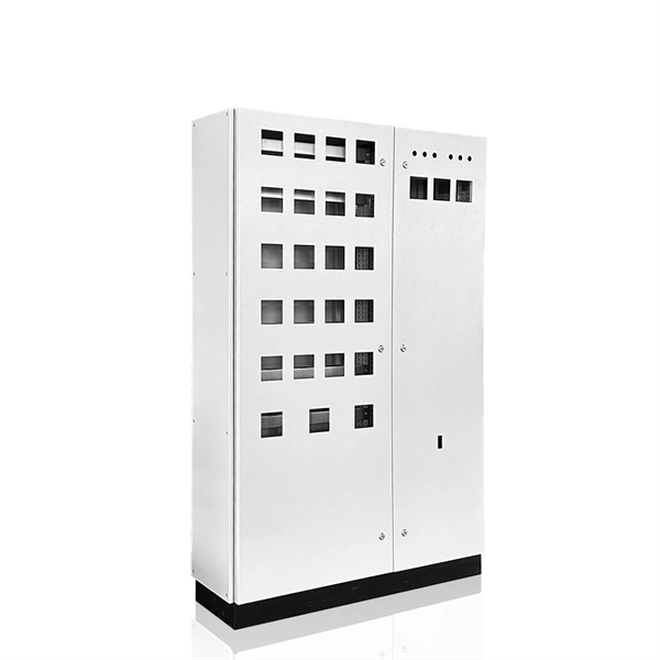
Electrical Box, Polycarbonate;Carbon Steel (Fastener) Material, Beige/Tan, SB Model, 61 Cu. In Capacity, 3 Gang, Rectangular, 1/2 In Knockout Size, 2 Knockouts, Internal Screw, 5-13/16 In Length, 3-9/16 In Width, 3-3/4 In Height, 3 LB. You can search for a variety of international and national standards for Vanuatu in the catalogue below. Entering this and that into the search form will return results containing both "this" and "that". 4 KV Substation of the ratings indicated above. These Distribution Cabinets are to be outdoor type nd to be fabricated out of 2 mm GI sheet steel. The body of the boxes shall have sufficient re- enforcement with suitable size of channels keeping a provision for fixin andle conforming to general. le pole Isolator (Switch Disconnector), conforming to relevant latest I. The supplier shall indicate makes and types of offered isolator in GTP. The Switch disconnector to e provided. The objective of this Specification is to establish standards and codes of practice that are required to be adhered to by both Contractor and Client in the design, supply and installation of LV Switchgear and Distribution Boards, on all Transnet Pipelines Sites. SCOPE This document describes as.
[PDF]

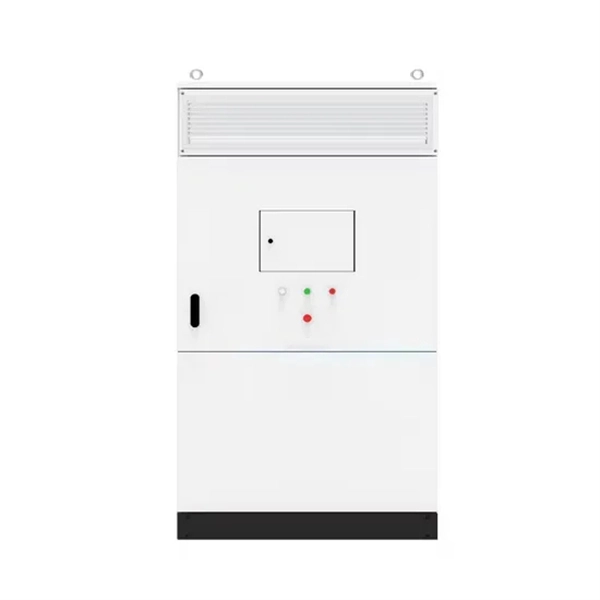
Découvrez les solutions innovantes de Solax Power disponibles à Madagascar. Specializes in the supply of electrical transmission and distribution equipment and components. A leading manufacturer; solution provider; repairer; and distributor of electromechanical equipment in Africa. Specializes in R&D of electric power technology; equipment manufacturing; and engineering. How does 6W market outlook report help businesses in making decisions? 6W monitors the market across 60+ countries Globally, publishing an annual market outlook report that analyses trends, key drivers, Size, Volume, Revenue, opportunities, and market segments. This report offers comprehensive. We offer a broad product line including Control, Step Down, Step Up, Copper, Cast Resin, Oil Filled, Power, Lighting, Induction Furnace, Rectifier, Single and Three Phase, Air/Oil Cooled Transformers, etc. along with AC/DC, Line or VFD Chokes. We have a professional staff that we constantly. power supply Companies and Suppliers serving Madagascar |. Bosch Industriekessel GmbH, a Bosch Thermotechnik GmbH company, has been developing and manufacturing project-specific heating and process heat systems for more than 150 years. In keeping with its “Invented for life” principle, Bosch.
[PDF]
