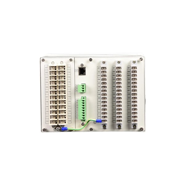
In an Ethernet patch panel diagram, each port on the patch panel is represented by a numbered or labeled square or circle. The diagram typically includes details such as the port numbers, cable types, and the devices connected to each port. Ethernet patch panel diagram is a visual representation of the connections between Ethernet cables and network devices, such as switches and routers. It provides a clear overview of how the network is structured, allowing network administrators to easily troubleshoot and manage the network. This information can be used to track the location of devices, their serial numbers, and their IP addresses. Change Management: Patch panel connection diagrams can be used to track. A patch panel is an essential component in a network system that provides a central location for connecting multiple devices or cables. The patch panel serves as. A pair of managed Gigabit Ethernet rack-mount switches, connected to the Ethernet ports on a few Panduit patch panels using Category 6 patch cables. (All equipment is installed in a standard 19-inch rack. Each port has a patch connection that links it to another port in another part of your building.
[PDF]
Electric power distribution systems are designed to serve their customers with reliable and high-quality power. The most common distribution system consists of simple radial circuits (feeders) that can be ove.
[PDF]

Non-polarizing beamsplitters are specified by their splitting ratio, i. the ratio of P-polarized light to. A beam splitter or beamsplitter is an optical device that splits a beam of light into a transmitted and a reflected beam. It is a crucial part of many optical experimental and measurement systems, such as interferometers, also finding widespread application in fibre optic telecommunications. a laser beam) into two (or sometimes more) beams, which may or may not have the same optical power (radiant flux). Different types of beam splitters exist, as described in the. The collimated incident laser beam passes through the beam splitter, and the output beam is emitted at a specific separation angle on the output beam array. The following figure is an introduction to the basic settings of a beam splitter. Circular beamsplitters, plate beamsplitters and cube beamsplitters can be purchased for polarizing or non polarizing beamsplitting. Beamsplitters are optical components used to split incident light at a designated ratio into two separate beams.
[PDF]

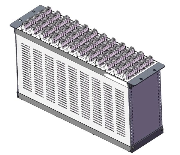
Cable Trays* — Max two 24 in. (610 mm) wide by max 6 in. (151 mm) deep open-ladder cable tray with channel-shaped side rails formed of 0. 54 mm) thick aluminum or min 0. In practice, cable tray dimensions are a system of interrelated measurements —width, depth, length, and material thickness—that directly affect cable fill compliance, heat dissipation, structural loading, and long-term expandability. From an engineering standpoint, cable tray dimensions are not. Perforated Cable Tray System expertly constructed from high-grade stainless steel, offering exceptional durability and resistance to corrosion. With side height 100mm. A properly designed and installed cable tray system will provide. Studs — Wall framing to consist of wood studs or channel shaped steel studs. Wood studs to consist of nom 2 by 4 in. Additional studs shall be used to completely frame. Best Size: Here, deep trays (75mm to 150mm) are used since power cables are typically thick and heavy. Data cables, such as your Wi-Fi or computer ones, are extremely sensitive. They do not get hot; however, they do not like to hang or sag. In case a data cable folds in an excessive manner, the. ect the minimum bend ra-dius for cables as they exit the bottom of the cable tray. A rung spacing of 6 to 9 inches (150 to 230 mm) is preferable when the cable tray cont d for instrumentation and control applications that require additional protec eferred to support and protect numerous small.
[PDF]
This map shows where fiber internet service is available across the United States from all providers. Use the map controls to color by number of fiber providers or by maximum fiber speed available. Fiber-optic internet is the fastest and most reliable type of internet connection available. It uses. Let us show you the fiber data that is currently available! As one of the leading fiber location databases, FiberLocator conveniently provides you with detailed maps and information on hundreds of carriers, thousands of data centers and hundreds of thousands of on-net buildings to quickly grow and. Ask about ICT infrastructure, broadband data, or interact with the map. Show me range to terrestrial fiber nodes on the map? Is the ITU building in Geneva Switzerland within 10 km of a fibre node? Start measuring on the map to see calculations here. Analyze network nodes within a 10 km radius using. The most recent North American Fiber Deployment Report by RVA LLC Market Research & Consulting (RVA) released in January 2025 presented more records for the progress of fiber across America. A new annual record of 10. homes were passed in 2024. The FCC reviews the data and then publishes.
[PDF]

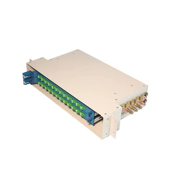
An Optical Splitter, also known as a beam splitter, is a passive optical device that divides a single input optical signal into two or more output signals. Conversely, it can also combine multiple signals into one. Knowing the difference between a splitter and an optical coupler helps you build better networks. You make your network work better when you pick the right device for each job. You can connect many users to one port with 1:n or 2:n splitters. By dividing a single optical signal from a central Optical Line Terminal (OLT) into multiple outputs for Optical Network Terminals (ONTs) at users' homes, splitters eliminate the need for dedicated fibers to each residence—slashing infrastructure costs while scaling network reach. This guide. In a Passive Optical Network (PON), a single optical fiber carries massive amounts of data using light. Signal Input: The fiber splitter receives the optical signal from the upstream network node and enters the splitter through the input fiber. Signal Distribution: Inside the splitter, according to the design structure and different. Splitters are passive optical devices that divide or combine optical signals, and they come in various types, including power splitters, uneven splitters, and wavelength-division multiplexing (WDM) splitters. Each type serves specific applications, enabling efficient use of optical infrastructure.
[PDF]

A ladder type cable tray tee is a fitting used to create a branch in a cable tray system, allowing cables to be routed in three directions. Its "T" shape provides a secure and efficient way to split cables from a main tray into two separate paths, ensuring organized and flexible. A cable tray tee and tee cover are components used in cable management systems to support and protect electrical and data cables. Here's a brief explanation of each:. Rigid steel cable tray tee fitting with zero tangent, safety bottom, and full accessory support. ventilation to heat producing cable such as power communication and other with the same or different width of the cable run. All fittings are available in sizes and types corresponding to the straight cable tray sections. These fitting are including: elbow, horizontal cross, vertical inside. NOTE : Equal or un equal tees can be supplied. When ordering state widths W1xW2xW3.. Office: 147/22 Nguyen Sy Sach Street, 15 Ward, Tân Binh Dist, HCMC,VN. Is it possible to connect 2 cabletrays with a "branch piece (left picture)" instead of a "tee (right picture)". The tee has 3 connectors, the branch piece only has 1 connector. I would like to ajust the "Type properties -> Fittings -> Tee" with the branch family, but can't get it accomplished.
[PDF]

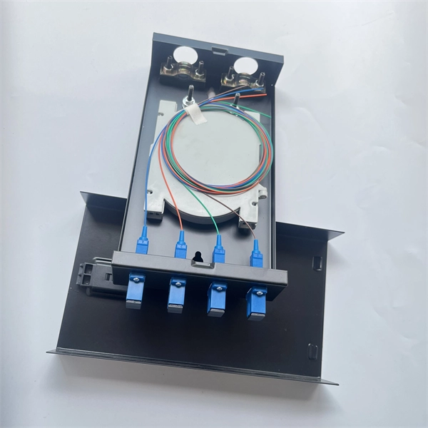
When you look at a fiber optic cable, the outer jacket color instantly tells you what type of fiber is inside. This color-coding system is standardized under TIA-598-C, making it easier for technicians and installers to identify cables at a glance. By adopting the TIA/EIA‑598C standard, you gain a universal “language” of colors that speeds identification, reduces miswiring, and enhances safety across cable jackets, connectors, buffer tubes, and splice trays. Error Reduction: A standardized palette prevents costly mis‑splices and. In fiber communications, the color of the fiber is not only an eyes-only indicator—it is actually used for determining the quantity, type of the fiber, and use of the fiber. Every fiber is color-coded, and this is a very crucial detail in the installation process, maintenance procedure, and. The fiber optic color codes refer to a standardized system used to identify individual fibers within a particular cable. These codes ensure correct organization and connectivity during installation or maintenance processes. The colors typically follow a color scheme established by industry. To solve this, the industry relies on an authoritative color-coding system: the EIA/TIA-598 Standard, which provides unified guidelines for identifying optical fibers, cable jackets, buffer tubes, and connectors.
[PDF]
How to connect multiple switches in a network with clear steps and tips for effective setup and configuration. Switches operate at the data link layer of the OSI model, forwarding packets of data between devices based on their MAC addresses. Switches come in various shapes and sizes, ranging. Cascading switches refers to the process of connecting multiple switches together in a series, effectively expanding the network's capacity and reach. This hierarchical connection allows for efficient and seamless communication between devices, regardless of their physical location within the. In the world of networking, Ethernet switches are integral components that provide the necessary interconnects for our devices. Sometimes, one switch is not enough to meet our needs, whether in terms of port number, specific functionalities, or both. Essentially, a LAN switch sets up a series of temporary networks that span only the two devices currently exchanging data. Depending on the configuration, connecting multiple switches can also. When one switch cannot meet the number of ports and a specific functional requirement, usually users will connect multiple Ethernet switches together, so how to connect multiple Ethernet switches together during network deployment? Three common types of connections are currently available:.
[PDF]