A beam splitter or beamsplitter is an optical device that splits a beam of light into a transmitted and a reflected beam. It is a crucial part of many optical experimental and measurement systems, such as interferometers, also finding widespread application in fibre optic telecommunications. DesignsIn its most common form, a cube, a beam splitter is made from two triangular glass which are glued together at their base using polyester,, or urethane-based adhesives. (Before these synthetic,. Beam splitters are sometimes used to recombine beams of light, as in a. In this case there are two incoming beams, and potentially two outgoing beams. But the amplitudes. For beam splitters with two incoming beams, using a classical, lossless beam splitter with Ea and Eb each incident at one of the inputs, the two output fields Ec and Ed are linearly related to the inputs thro.
[PDF]

Integrated Power Services (IPS) is your power partner for operating reliability. We repair, rebuild to “like new” condition, and remanufacture electrical equipment. We also supply low- and medium-voltage circuit breakers, switchgear, transformers, and related parts, both new and obsolete. National. From sales to repair to field services, we support reliable energy solutions across clean and traditional power systems. Harnessing energy from clean and traditional sources, we deliver tailored solutions for reliable and efficient power generation systems. Whether it's electromechanical equipment. Integrated Power Supply provides a stable and reliable AC and DC power supplies against all AC mains variations or interruptions. Enhance safety in train operations (by avoiding blanking of signals). It consists of the following modules: The. Independent Power Setup: Critical instruments or instrumentation systems are equipped with dedicated uninterruptible power supplies (UPS). This ensures continuous power during unexpected outages in the main power grid, safeguarding data integrity and preventing equipment shutdown. For instance. At their base level, residential, commercial, and industrial automation complexes must incorporate a wide range of security, safety, and emergency communications systems for insurance requirements and local building codes, and to receive a certificate of occupancy.
[PDF]
Whether you're building a commercial setup or upgrading an industrial plant, proper cable tray installation ensures neat wiring, safe access, and easy maintenance. But before you lay the first tray or clamp down a single cable, you need a solid plan. This guide breaks. This method statement covers the site installation of the cable tray & ladders and the requirements of checks to be carried out. The Cable Tray system is installed in electrical rooms, plant rooms, and service corridors. This guide breaks down the process step by step. This process is integral to determining the optimal arrangement and configuration of cable trays, which are essential for routing and supporting electrical cables within buildings and. 1. 0 This method statement will serve as a minimum guideline to carry out the Cable Tray Installation activities for commercial buildings, plants and refineries in accordance with Project Drawings and Specifications. This document outlines the key requirements for cable tray layout, installation, and fireproofing in industrial and commercial environments. Route. Below is the detailed cable tray installation method statement not only for cable tray but also applicable for GI ladder and trunking for indoor and outdoor applications and in service rooms like pump rooms, electrical rooms and plant rooms etc. All materials intended for cable tray, ladder and.
[PDF]

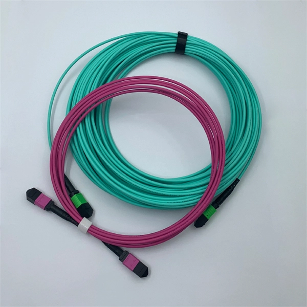
In short length cables a visual fault locator (VFL) can find where the cut is or find the bad connector at patch panels. For longer distance cables, the use of an OTDR is required. Once the fault is located, fusion splicers and splice-on connectors can be used to complete the repair. Fiber optic cables are the backbone of modern networks, delivering fast and reliable data transmission. Accidental cuts, breaks, or other damage can disrupt your network and cause costly downtime. With the right tools and techniques, you can efficiently repair damaged fiber cables and restore. Fiber optics offers advantages like EMI immunity and low attenuation (0. 2 dB/km), but it's fragile—susceptible to breaks, bends, and contamination. Repairs focus on restoring the light path with minimal signal loss (<0. A fusion. Visual inspection and specialized tools like OTDRs, OPMs, and VFLs are essential for identifying and locating physical damage or faults in fiber optic cables. Emergency restoration planning involves implementing backup power solutions, network redundancy planning, and strategies for prompt. Fiber optic cables are critical components of modern communication networks, transmitting vast amounts of data at lightning speeds.
[PDF]
BSLI is an original equipment manufacturer (OEM) of custom electrical power distribution products. BSLI guarantees its customers fast, personalized service, quality components, and custom-designed equi.
[PDF]
At Multilink, we offer traffic power solutions to keep traffic signals, camera equipment, illuminated street signs and other tech up and running. Power traffic signals, camera equipment, lighting and other t.
[PDF]

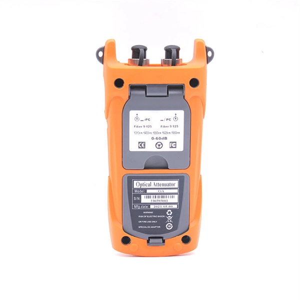
To use a power meter for fiber optic testing, always clean connectors first with lint-free wipes or click-to-clean tools. Select the correct wavelength and set your reference. You measure optical power in dBm or insertion loss in dB. Consistent procedures ensure accuracy. Verify light travels from. The most basic fiber optic measurement is optical power from the end of a fiber. This measurement is the basis for loss measurements as well as the power from a source or presented at a receiver. Typically both transmitters and receivers have receptacles for fiber optic connectors, so measuring the. An optical power meter measures the strength of light traveling through a fiber optic cable, giving you a reading in dBm (decibels relative to one milliwatt). This article will guide you through the methods, instruments, and key considerations for measuring fiber. Fiber optic cabling is the high-performance core of today's datacom networks. As network speeds and bandwidth demands increase, fiber performance requirements have become more stringent. Fiber testing is more important than ever. An OPM uses a photodiode to generate an electrical current proportional to optical power.
[PDF]

Built on Huawei's unified software platform and equipped with high-performance fully programmable chips, they deliver abundant features including Service Roam, VXLAN and iFlow, helping customers build high-quality campus bearing networks for the all-wireless era. Leveraging the Service. CloudEngine S5735-S-V2 switches support simplified operations and maintenance (O&M), and flexible Ethernet networking. It also provides enhanced Layer 3 features and mature IPv6 features. For example, it can be used as an access or. CloudEngine S5736-S series switches are next-generation standard all-optical GE access switches that provide 24-port and 48-port models, and provide four 10GE ports and one extended slot(optional). CloudEngine S5736-S series all-optical GE access switches are developed based on next-generation. Comprehensive analysis of Huawei's revolutionary optical switch innovations for 2025, including data center all-optical switching, silicon photonics integration, quantum-compatible switches, and 5G-Advanced network solutions. The port supports the PoE function. It sends and receives service data at 1000 Mbit/s or 10 Gbit/s.
[PDF]
Discover premium Fiji power adapters with 100% on-time delivery. Shop universal AC DC adapters (5V-24V) for desktop, CCTV, router & more. Durable, multi-plug compatible. [Energy Efficient and Environmentally Friendly]: Not only does the Charger by PowerHOOD deliver impressive performance, but it is also energy efficient. Explore a wide range of our Fujifilm AC Power Adapter selection. Find top brands, exclusive offers, and unbeatable prices on eBay. Shop now for fast shipping and easy returns!. Unleash boundless energy with the BLUETTI AC200P L Portable Power Station, your ultimate power companion for adventures and emergencies alike. 8Wh Capacity with 4,000+ Life Cycles: Perfectly designed for daily power needs or as a reliable backup during outages. Fiji operates on 240V at 50Hz using Type I plugs, the three-pin angled standard found across Australia, New Zealand, and several Pacific nations. US travelers need a plug adapter since American Type A/B plugs won't fit Fiji's outlets. The higher voltage means faster charging for compatible devices. - Rack Height: 4U - Output Connections: (1) Hard wire 4-wire (2P + N + E), (1) Hard wire 3-wire (H N + E) - Nominal Output Voltage: 120V, 200V, 208V, 230V - Nominal Input Voltage: 200V, 208V, 230V, 480V 3PH - Input Connections: Hard wire 3-wire (2P + E), Hard wire 3-wire (H N + E), Hard wire 4-wire.
[PDF]
Electric power distribution systems are designed to serve their customers with reliable and high-quality power. The most common distribution system consists of simple radial circuits (feeders) that can be ove.
[PDF]

This article will introduce passive optical networks (PON), in which we will introduce everything about OLTs, ONTs, ONUs, and ODNs, including their operation principles and functions. PON (Passive Optical Network) refers to a fiber optic network built using a point-to-multipoint topology and fiber. Active Optical Networks (AON) and Passive Optical Networks (PON) make FTTH broadband connections possible. To date, most FTTH deployments in planning and deployment have used PON to save on fiber costs. PON has attracted much attention in recent years due to its low cost and high performance. There are no specific requirements for this document. This document is not restricted to specific software and hardware versions. The information in this document was created from the devices in a. OLT, ONU, ONT, and ODN are key components and acronyms used in Passive Optical Network (PON) architecture, which is a popular technology for delivering high-speed broadband services. This technology is widely used in fiber-to-the-home (FTTH) and fiber-to-the-premises (FTTP) deployments. In contrast to AON, multiple customers are connected to a single transceiver by means of. An Optical Distribution Network (ODN) serves as the bridge in a Passive Optical Network (PON), transmitting optical signals from the Optical Line Terminal (OLT) to the Optical Network Unit or Terminal (ONU/ONT), thus linking a service provider's core network to end-users (residential or business).
[PDF]
Housing Integrity: Cracked, melted, or physically broken outer casings. Electrical Failure: Severe internal burn marks or "fried" traces that prevent a safe rebuild. Completeness: Units that have been scavenged for internal parts or are missing proprietary hardware. This document describes how to identify, isolate, and troubleshoot symptoms of hardware failures on Catalyst 9600 Supervisors and Line Cards. There are no specific requirements for this document. The information in this. If the switch has rebooted unexpectedly, you can follow the steps to troubleshoot the hardware. If your core looks different. This topic covers the steps for troubleshooting bootup, crash, network, software, and audio issues related to the Q-SYS Core 110f processor and Cinema Core 110c processor. It details what information to collect post-event to help identify the root cause. Requirements and Components Used Requirements: None specific to hardware/software versions. Lab. Hardware faults on CE switches include power supply faults, fan faults, card power-on failures, unexpected card restarts, abnormal optical module status, and abnormal interface status. The following information helps you quickly locate hardware faults. Common Causes of Power Supply Faults Common.
[PDF]

Key finding: This paper develops analytical models and design procedures of ultra-wideband Wilkinson power dividers using linearly tapered transmission lines (TTLs) which provide size reduction and broadband performance. Read more. Power dividers are the passive electronic equipment used for splitting the power. They are now being employed in a variety of communications applications such as telephonic, antennas configurations, mobile connectivity, internet technology, & optics, etc. They come up with very low loss, operate at. RF and microwave power splitters and dividers create two copies of the same signal, while ideally preventing crosstalk between the outputs. Doing this with minimal loss while maintaining signal integrity is a challenge. In this article we explain how power splitters work and what the tradeoffs are. The rise of wireless connectivity requirements for applications such as Internet of Things (IoT), cellular, and automotive electronics is resulting in systems that are increasingly using RF signals, components, and subsystems. Often, designers need to direct these signals to more than a single. A power divider is a passive electronic device used in radio frequency (RF) and microwave applications to split an input signal into multiple output signals with equal or specified power levels, while maintaining impedance matching to minimize signal reflection and loss. How can power dividers.
[PDF]

This AutoCAD DWG file includes a complete Single Line Diagram (SLD) of a Distribution Board, showing circuit breakers, wiring connections, and load distribution for lighting, power, and mechanical systems. Knowledge of the basic electrical power distribution system and its components will help the operator understand the importance of electrical power distribution systems. Failure-free power e. Overlapping protective zones a. Protective relays A single, or one-line. A power distribution box (also called PDU or distro) directs electricity from a main source to multiple circuits. It acts like a hub or traffic controller, managing power flow to different areas or devices. Key components include circuit breakers, fuses, bus bars, and internal wiring for safety and. Check electrical parameters: First understand the basic electrical parameters of Distribution box so that you can have a general understanding of the capacity and performance of the distribution box. Analyze the incoming line part: Determine the incoming line source of the distribution box and. ndards and conformity assessment activities in the United States. ANSI facilitates and promotes voluntary consensus standar rty or economic loss due to fire, electrical and related hazards. Now, let's look at how consumers use electrical power. What is a Electrical Power Distribution System? 1. Power supply is received from LT panel and distributed to the outgoing feeders for utilization.
[PDF]

The core measurement procedure follows five steps: Turn on the meter and let it warm up. Most meters need a brief stabilization period before readings are reliable. Check your model's manual, but a minute or two is typical. Set the wavelength to match your light source. Fiber loss is the difference between the power when light is coupled from the transmitting end to the fiber and the power when the light reaches the receiving end. Generally speaking, when measuring the. An optical power meter measures the strength of light traveling through a fiber optic cable, giving you a reading in dBm (decibels relative to one milliwatt). The basic process is straightforward: turn the meter on, set it to the correct wavelength, clean your connectors, plug in, and read the. A power meter and light source are essential test tools that work in tandem to measure fiber optic cable loss and evaluate the quality of optical links. They provide the data necessary to quantify signal loss and pinpoint issues that could impact network performance. Here's how they work: A power. You measure optical power in dBm or insertion loss in dB. Verify light travels from transmitter to receiver. We'll give you the basic information you need and provide some printable references.
[PDF]