Shop the Smart Switch collection from Platinum Imports Inc: supplying a wide range of products for Barbados homeowners and businesses seeking to outfit or upgrade their kitchens, bathrooms, plumbing, and electrical fixtures. Shop online or visit our air-conditioned showrooms in Designers Hub and. We lead the industry in optical switch technology, delivering the lowest insertion loss (0. 2 dB), fastest switching speed (10 ns), broadest wavelength range (300–2400 nm), widest fiber compatibility, highest optical power handling (50 W), and space-qualified reliability. Backed by over 25 years of. Since we are the longest-standing security system provider in Trinidad, we already know which companies provide the best equipment. We are partners with Hikvison, Seco-Larm, DSC, Kantech and VDS - leading security equipment manufacturers. We are committed to continuously strengthening our brands and. What is an optical switch? An optical switch, also known as an optical line switching device (automatic switching type optical patch panel), is a device that enables the network to be always connected. Any communication protocol (Ethernet, ATM, etc. ) can. Control your lights from anywhere with the TP-Link Kasa Smart Light Switch—easy scheduling and voice control built-in.
[PDF]

A ceramic sleeve is a small, cylindrical element employing zirconia, which is a strong, low thermal expanding ceramic used in a fiber optic system to locally align and hold the interface between the fibers or connectors. It ensures precise alignment. Known for their high-temperature resistance, wear resistance, and chemical stability, ceramic sleeves have become a key element in applications spanning communications, electronics, automotive, aerospace, and industrial systems. The industry is developing in a diversified manner, connecting raw. Most of the ferrules used in optical connectors are made of ceramic (Zirconia) material due to some of the desirable properties they possess. Kyocera's extrusion molding process creates ferrules with excellent coaxiality, and our precision machining ensures excellent concentricity with precise. Alignment sleeves are the primary mechanical reference inside a fiber optic adapter. Their role is to constrain lateral offset, angular deviation, and axial separation between mating ferrules, directly determining insertion loss and return loss stability. Historically, both ceramic and phosphor. The global market for ceramic sleeves is experiencing robust growth, projected to reach an estimated $287 million by 2025. This expansion is fueled by an impressive CAGR of 20. 5% during the study period. The primary drivers for this surge are the increasing demand for high-performance optical.
[PDF]

NPO (Near-Packaged Optics) is a transitional technology bridging traditional pluggable modules and CPO. It integrates the optical engine and GPU chip side-by-side on the same high-performance PCB or organic substrate, connected via ultra-short high-speed circuits. Its core concept is to remove digital processing units such as DSPs and CDRs from the module, constructing a purely analog "linear direct-drive" optical link. In the LPO architecture: The transmitter uses a high-linearity driver chip to directly drive the optical modulator, converting the. Near-packaged optics (NPO) helps send data faster. It puts the optical engine close to the switching chip. This makes things work better. NPO lets you upgrade easily. You do not have to redesign your whole system. It lowers energy costs. Among the emerging technologies, LPO (Linear Pluggable Optics), NPO (Near-Packaged Optics), and CPO (Co-Packaged Optics) represent three important stages in the evolution of next-generation data center optical networking. Understanding how these architectures differ is essential for designing. Traditional optical modules typically rely on DSPs (Digital Signal Processors) to handle signal equalization, retiming, and compensation, mitigating attenuation and distortion during transmission. They are not concepts at the same level, but rather.
[PDF]

The Intellinet Network Solutions 10 Gigabit Fiber SFP+ Optical Transceiver Module (model 507479) is fully hot-pluggable, and that allows you to install the module without rebooting your network switch for uninterrupted network traffic. Intellinet Network Solutions 10GBase-LR Fiber SFP+ Optical Transceiver Module, model 507479, is the right choice when it comes to connecting two buildings at 10 GbE speeds with single mode fiber. That's a 10 Gbps connection up to a distance of 10 km (or 6.2 miles). The transceiver comes in a mini-GBIC form factor, making it ideal for environments that require many fiber connections by taking up less space in your cabinet and/or computer room. Compatibility in your network is everything, and the Intellinet Network Solutions SFP+ Transceiver Module (model 507479) delivers. Use it with any Intellinet Network Solutions SFP+ equipped network switch or any other MSA compliant SFP+ enabled switch. And since the Intellinet Network Solutions SFP+ transceiver module is set to broadcast the vendor. The Intellinet Network Solutions 10 Gigabit Fiber SFP+ Optical Transceiver Module (model 507479) supports standard digital diagnostics monitoring (DDM) functions, also known as digital optical monitoring (DOM). This gives the user the ability to monitor parameters of the SFP, such as optical output power, optical input power, temperature, laser bia.
[PDF]

An Optical Splitter, also known as a beam splitter, is a passive optical device that divides a single input optical signal into two or more output signals. Conversely, it can also combine multiple signals into one. Knowing the difference between a splitter and an optical coupler helps you build better networks. You make your network work better when you pick the right device for each job. You can connect many users to one port with 1:n or 2:n splitters. By dividing a single optical signal from a central Optical Line Terminal (OLT) into multiple outputs for Optical Network Terminals (ONTs) at users' homes, splitters eliminate the need for dedicated fibers to each residence—slashing infrastructure costs while scaling network reach. This guide. In a Passive Optical Network (PON), a single optical fiber carries massive amounts of data using light. Signal Input: The fiber splitter receives the optical signal from the upstream network node and enters the splitter through the input fiber. Signal Distribution: Inside the splitter, according to the design structure and different. Splitters are passive optical devices that divide or combine optical signals, and they come in various types, including power splitters, uneven splitters, and wavelength-division multiplexing (WDM) splitters. Each type serves specific applications, enabling efficient use of optical infrastructure.
[PDF]
An optical modulator is a device which can be used for manipulating a property of light — often of an optical beam, e. Depending on which property of light is controlled, modulators are called intensity modulators, phase modulators, spatial light modulators, etc. The beam may be carried over free space, or propagated through an optical waveguide (optical fibre). This lets devices send lots of data fast and without mistakes. This process dynamically alters properties of an optical carrier wave—such as amplitude, phase, frequency, or polarization—to embed data. These devices play a crucial role in modern optics and photonics, enabling the manipulation of light for various applications. An optical modulator is a critical component in the realm of photonics and optical communications, playing a pivotal role in manipulating light to encode. Optical modulation allows one to control an optical wave or to encode information on a carrier optical wave. The inverse process that recovers the encoded information is demodulation. According to the.
[PDF]
The Total Cost of Ownership (TCO) for Passive Optical LAN (POL) is often wrongly seen as high. Meanwhile, Optical LAN can be cheaper in rip & replace use cases, even in brownfield scenarios. Moreover, the long-term return is significant. Hardware and deployment. Often the lower costs are a result of Passive Optical LAN (POL) ability to: The Association for Passive Optical LAN (APOLAN) Technology Committee members recently completed a POL cost comparison study. They did so by analyzing the cost of POL parameters (e. 4-port PoE ONTs, ONTs shared in. The elimination of costly IDFs is one of many capex-reducing elements that users enjoy when they switch to POL, finds recently released cost comparison produced by the Association for Passive Optical LAN (APOLAN). There are no IDFs at this high-end. Passive Optical LAN replaces copper and multi-tier switches with fiber-optic cabling and passive optical splitters based on FTTH GPON/XPON technology. POL transforms a LAN into a simple and flat fiber cabling network. POL covers large building projects and long-distance transmission without the. The Association for Passive Optical LAN (APOLAN) announced the results of it Passive Optical LAN Cost Comparison study, conducted to illustrate the possible economic advantages of POL over traditional enterprise networks based on Category cable.
[PDF]

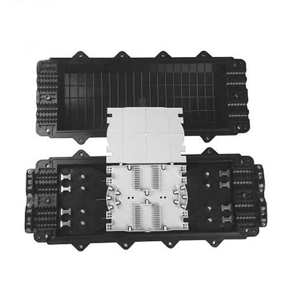
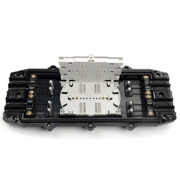
Here's a step-by-step guide to help you set up your fiber distribution box seamlessly: Before installing the fiber distribution box, ensure that your optical cables are properly prepared for connection. The optical fiber distribution box allows people to easily access the optical fibers in the box, and can well protect the optical fibers. In addition, the drawer structure also facilitates high-density wiring and good cable management. However, because optical fibers are fragile and can be easily. Keeping this page as a placeholder for now. Have any questions? Talk with us directly using LiveChat. Fix the rack to the ground with expansion bolts. Top installation: Dimensions of four connection holes on the top according to the. This instruction describes the installation of the Fiber Distribution Frame (FDF) manufactured by Corning Optical Communications. To order accessories that are purchased separately, contact Corning Optical Communications customer care for assistance. Read and understand this procedure (as well as. Optical fiber distribution frame is the wiring connection equipment between optical cable and optical communication equipment or between optical communication equipment. Distribution boxes are especially essential for FTTH networks, where they enable the efficient connection and management of optical fibers from a central.
[PDF]

An optical transceiver module, often simply called an optical module, acts as a signal conversion interface in fiber optic networks. It transforms high volumes of electrical signals into optical signals for transmission over fiber cables, or reverses the process at the receiving. In the world of fiber optic communications, optical transceiver modules play a pivotal role as interfaces that convert electrical signals to optical signals and vice versa. If you're dealing with data centers, telecommunications, or AI networking, grasping the key parameters of an optical. Optical transceivers are efficient in changing signals. These modules have many parts, each with a specific functions: Takes in electrical signals to change them. Powers lasers or LEDs to send light signals. Combines many light signals into one for. An optical transceiver, a crucial device utilized in optical communication, is an optoelectronic element, allowing the interconversion of optical and electrical signals during the information transmission. Acting as the "heart" of fiber-optic networks, these modules—ranging. This comprehensive guide breaks down the internal structure, core components (TOSA, ROSA, lasers), and operational mechanisms of SFP optical modules, enriched with technical insights and real-world applications.
[PDF]

Built with GF's advanced silicon photonics technology, the SCALE CPO solution utilizes both coarse and dense wavelength-division multiplexing (CWDM, DWDM) for bi-directional data transmission over each optical fiber for significant improvements in bandwidth density and system. Built with GF's advanced silicon photonics technology, the SCALE CPO solution utilizes both coarse and dense wavelength-division multiplexing (CWDM, DWDM) for bi-directional data transmission over each optical fiber for significant improvements in bandwidth density and system. MALTA, N., May 04, 2026 (GLOBE NEWSWIRE) -- GlobalFoundries (Nasdaq: GFS) (GF) today announced the introduction of its SCALE™ optical module solution for co-packaged optics (CPO). GF's SCALE solution, or Silicon photonics Co-packaged Advanced Light Engine solution, is the industry's first Optical. MALTA, N. 9, 2024: IBM (NYSE: IBM) has unveiled breakthrough research in optics. These pressures are driving renewed momentum behind co-packaged optics (CPO). According to LightCounting, sales of lasers and photonic integrated circuits for optical transceivers are expected to grow from $2. 9B by 2029, fueled largely by AI data centers.
[PDF]

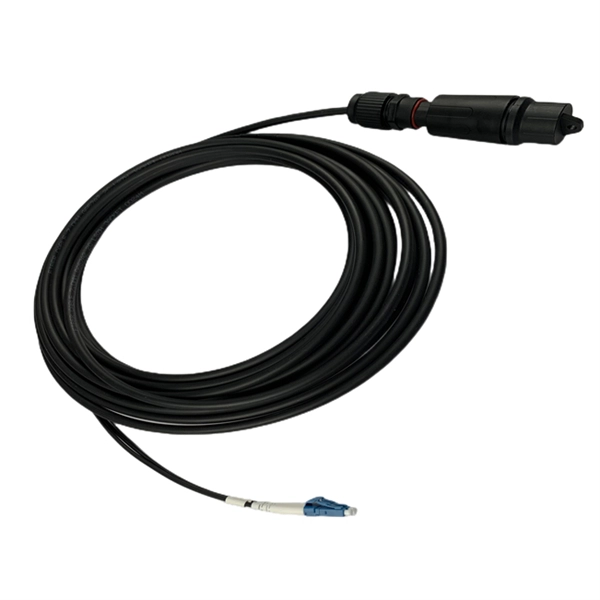
With protective doors, dust-proof 2). Suitable for many types of modules, used in cabling work area subsystem 3). Embedded type surface, easy for installation and removal 4). Available for fiber optic SC simplex or LC duplex and can be used in both surface mounted. 1). This termination box supports 0. 0mm pigtails and 2x3mm indoor drop cables. Discover the Welink FTB-1005: a high-quality 1 Core Fiber Optic Outlet for FTTH. RoHS certified, compact, durable, and easy to install. Compact Design: Space-saving footprint (86x86mm) ideal for residential and office wall mounting. Splice Protection: Integrated tray securely holds fusion. FTTH Terminal box is a compact fiber terminal for use at the final fiber termination point in the customer premises. It provides mechanical protection and managed fiber control in an attractive format suitable for use inside customer premises, A variety of possible fiber termination techniques are. 1 Core Fiber Optic Desk Terminal Box for SC, FC Adapter, Patch Cord or Pigtail Description: 1). It provides a secure and convenient location for fiber optic splicing, connecting the drop cable and the passive optical equipment of the optical network. protection and management for the FTTx network building. Features: Scope of application 3. Specification: Applications: 1 Core Fiber Optic Terminal Box is used as a termination point for the feeder cable to connect with drop cable in FTTx communication network.
[PDF]

Here at AFL we provide years of experience and excellent solutions for your hardware needs in both ADSS (All-Dielectric Self Supporting), OPGW (Optical Ground Wire) and SkyWrap cables. Please follow the links below for assistance in choosing your hardware. The aluminum Opti-LoopTM FOS for All Dielectric Self Support (ADSS) cable is available in 3 sizes. With more than one million units in service, Opti-Loop fiber storage systems lead the industry in quality and durability. All aluminum construction with continuous welds at crossbars and ends. Each. Also see our line of ADSS Fiber Optic Cable. © Copyright 2026 AFL. Our product experts are here to assist you. Get in touch with our team now. PLP transmission, distribution, substation, fiber optic, solar, and EV solutions protect and connect overhead electric power lines and communications networks. ADSS Anchor Tension Clamps are hardware fittings used to securely terminate and anchor ADSS fiber optic cables on poles or towers without damaging the cable. This is a type of self-supporting optical fiber cable that does not require any kind of support in distributing electricity from one point to another. As much as they may be independent, these cables are usually installed on poles and.
[PDF]

Fiber Optic Welding How To Joint Fiber Optic Cablesplicing fiber optic cable,fiber optic splice,fiber optic,fiber optics,fiber splice,how to splice,fibre opt. The optical fiber connection adopts the fusion splicing method. The whole process is similar to the welding of metal wires, and it is generally carried out by electric isolation. At the moment, there are two methods of connection: Thermal welding of optical fibers consists in bringing the ends of the conductor to melting using a fiber optic splicer, and more specifically - located inside the electrodes. The welded ends are then pressed and a weld is formed. The most work is waiting for installers, whose tasks can be divided into several stages: In this part, we will deal with the second stage, i. welding, which is considered to be one of the most difficult parts of installers' work in. Open the stripping tube and wipe the grease on the optical fiber with toilet paper and alcohol cotton. On the welding disc, make the optical fiber precoil first and cut the optical fiber into an appropriate length to facilitate the coil fiber work after welding. Add heat shrink tube. Procedure. Another method is to use the so-called mechanical welding. It uses special parts that are prepared in advance to connect the two ends. Thanks to this, you can connect two ends of the cable with a ready-made splice, without the need to use an optical fiber splicer. While this method may appear to be.
[PDF]
For TDM-PON, a passive optical splitter is used in the optical distribution network. In the upstream direction, each ONU (optical network units) or ONT (optical network terminal) burst transmits for an assigned time-slot (multiplexed in the time domain). In this way, the OLT is receiving signals from only one ONU or ONT at any point in time. In the downstream direction, the OLT (usually) continuously transmits (or may burst transmit). ONUs or ONTs see their own data through the address labels embe.
[PDF]
An optical time-domain reflectometer (OTDR) is an optoelectronic instrument used to characterize an optical fiber. It is the optical equivalent of an electronic time domain reflectometer which measures the impedance of the cable or transmission line under test. An OTDR injects a series of optical pulses into the fiber under test and extracts, from the same end of the fiber, light that is scatter. Reliability and quality of OTDR equipmentThe reliability and quality of an OTDR is based on its accuracy, measurement range, ability to resolve and. The common types of OTDR-like test equipment are: 1. Full-feature OTDR: 2. Hand-held OTDR and Fiber break locator: 3. RTU in RFTSs:. In the late 1990s, OTDR industry representatives and the OTDR user community developed a unique data format to store and analyze OTDR fiber data. This data was based on the specifications in GR-196, G.
[PDF]

