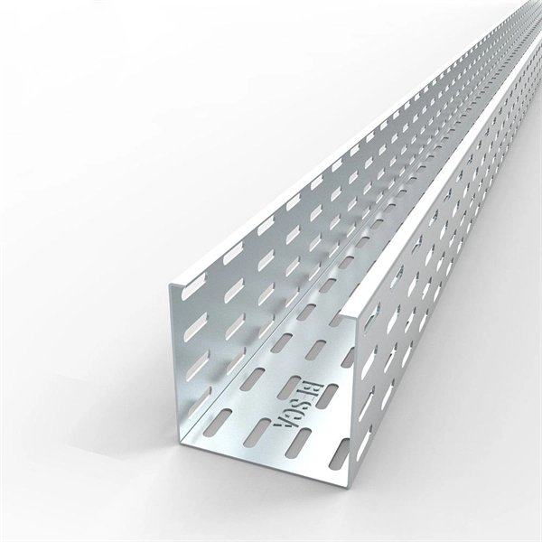
Proper planning for installing cable tray includes calculations based on loading, support systems, cable/wire fill and spacing, conductor types, securing of the cables and wire, and proper grounding and bonding are all important aspects of cable tray installation. How about organizing your wiring with a cable tray system? Smart move. Whether you're building a commercial setup or upgrading an industrial plant, proper cable tray installation ensures neat wiring, safe access, and easy maintenance. This guide covers the critical steps, from selecting the right electrical cable tray and performing accurate cable fill. Cable tray installation implies the construction of an electric road that will be safe. In order to get it right, installers are supposed to adhere to a plan that ensures that wires are kept cool and the building is stable. The beginning of success is to review the Bill of Quantities (BOQ) so that. Our solutions and products are made in the USA and our service and support can assist with any install or product selection questions that you may have. Here's what you'll learn: Planning: Assess cable requirements, calculate loads, and select the right tray system (ladder, trough, or wire mesh) based on factors like weight and environment. Proper installation of cables in trays is critical for maintaining an efficient and safe electrical system. This is why proper planning and execution are.
[PDF]

A neat, well-organized subpanel bundles wires to conserve space and improve access. Ideally, wire groups are installed in layers and wires are bent at right angles to buses or breakers. Label short sheathing sections (slugs) to indicate which circuits wires serve. A cluttered or messy junction box can lead to electrical hazards, such as short circuits or difficulty diagnosing issues later on. Whether you're a professional electrician or a DIY. Welcome to this live training session! ⚡ In today's tutorial, I'll be demonstrating how to arrange cables neatly inside a distribution bo. more See what others said about this video while it was live. After all, a well-organized junction box is like a well-organized sock drawer: you might not notice it, but when it's a mess, everyone knows. And let's be honest—nobody wants to dive into a rat's. Whether you're a homeowner or working with a residential electrician in Richmond VA, managing your cables properly makes your space look better, increases safety, and improves functionality. Learning how to keep wires organized not only improves the appearance of your space but also makes your. To ensure the aesthetic appearance of the wiring installation inside the electrical ready board box, the following points can be followed: Grouping and layering: Grouping and layering neutral, live, and ground wires to ensure clear and orderly routing of the lines. Horizontal and vertical: When.
[PDF]

The 6 terminal junction box wiring diagram provides a visual representation of how the various wires and connections should be made within the box. It shows the layout and arrangement of the terminals, as well as the color coding and labeling of the wires. Hey, in this article we are going to see the Single Phase Distribution Box Wiring Diagram and Connection Procedure. A distribution board or distribution box is where the main power supply is distributed to multiple loads. It provides a quick and easy reference guide to understanding the meaning behind each symbol. These symbols can represent different electrical components, such as switches, resistors. This technical article aims to take you on a journey through the fundamental terminals and other connecting elements of wiring diagrams and electrical schematics and to delve into the minute intricacies of the components that form them. From the familiar male and female terminals that form the. An electrical panel box, also known as a breaker box or a distribution board, is a crucial component of any electrical system. Whether you're an electrician or a DIY enthusiast, this guide will help you understand the basics of home electrical distribution. more Welcome to our. The Engineering Base terminal block diagram is a special template showing information about terminal blocks, terminals and their accessories. There are two methods for creating a terminal block.
[PDF]

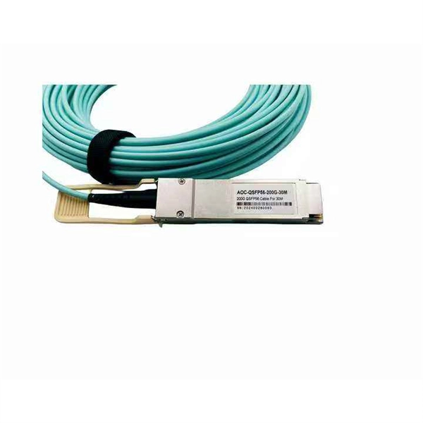
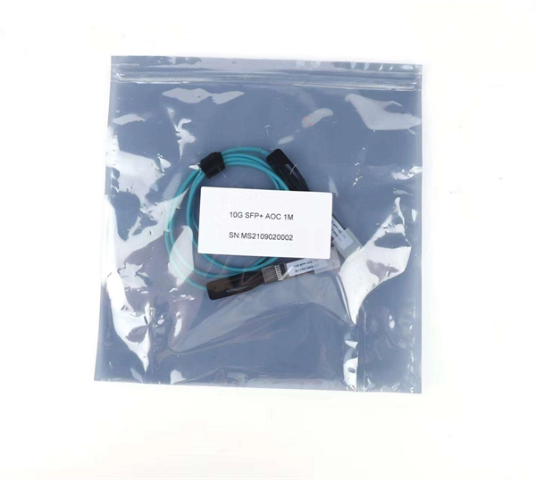
This comprehensive guide will explore the importance and benefits of this integration, provide an understanding of fiber optic cable and Ethernet ports, discuss their compatibility, and offer a step-by-step process for connecting them. Proper connection of fiber optic cables is essential to harness these benefits fully, as even minor errors can lead to significant performance issues like signal loss. This article will guide you through the necessary tools, materials, and methods on how to connect fiber optic cables effectively. Using an optical cable involves connecting it to the right equipment, ensuring proper installation, and testing the system for optimal performance. Here's a step-by-step guide on how to use optical cable effectively: 1. Check Compatibility of Equipment Ensure that your equipment (e., network. One powerful solution to achieve these goals is by connecting fiber optic cables with Ethernet ports. This comprehensive guide combines industry standards with field-tested practices to ensure you achieve a rock-solid. These transceiver modules are hot-swappable input/output (I/O) devices that plug into 100BASE, 1000BASE and 10GBASE ports (for SFP+), which connect the module port with the fiber-optic or copper network. The SFP transceiver modules are hot-pluggable I/O devices that plug into module sockets. The number one cause of signal loss in optical fiber installations is dirt on.
[PDF]

Optical return loss is the amount of light that is reflected back to the source, this reflected light is measured at each connector and splice at each point over the entire fiber link. This is always measured in dB (decibels) and will be displayed as a negative number. The closer the number is to. The polish of a singlemode fiber endface plays a significant role in reflectance. Understand what you need before you specify. The Institute of Electrical and Building the ORL story Electronics Engineers (IEEE) recently Within a fiber-optic channel or path-released new specifications within way. Optical Return Loss (ORL) in fiber optics refers to the amount of light that is reflected back toward the source in a fiber link. ORL is usually expressed in decibels (dB) as a positive value, with. Return loss (RL) is also called reflection loss. When high-speed signals enter or exit a part of an optical fiber, such as an optical fiber connector, discontinuity and impedance mismatch may cause reflection, which is the return loss of an optical fiber. Poor ORL is commonly caused by dirty connectors, poor splices, mismatched connector types, or damaged fibers. ORL is measured using ORL meters. Home Coherent Optics Optical Return Loss (ORL) Explained Comprehensive Guide to Understanding and Managing Back-Reflections in Fiber Optic Systems What is Optical Return Loss (ORL)? Optical Return Loss (ORL) is a critical parameter in fiber optic systems that quantifies the amount of light.
[PDF]
This video shows real on-site footage of electrical installation, demonstrating safe and standardized wiring methods used by professionals. more Learn how to wire a distribution box step by step!. Explosion-proof distribution boxes, vital terminal distribution equipment in power systems, play a crucial role in controlling and protecting industrial electricity in hazardous environments. Given their ubiquity, let's delve into the installation and wiring of indoor distribution boxes today. Choose the right box based on environment (indoor/outdoor), load capacity, and durability. Check for proper IP/NEMA ratings and material quality. These panels are commonly installed in areas like detached garages, workshops, basements, or home additions to manage localized electrical loads. Whether you're an electrician or a DIY enthusiast, this guide will help you understand the basics of home electrical distribution. What is Distribution Board? Distribution board. Common NEMA ratings include NEMA 1 (for basic indoor protection) and NEMA 4 (for corrosion resistance). If your distribution box is installed outdoors and exposed to rain and sunlight, you need to select an electrical enclosure with a higher protection level, such as models with IP66 or NEMA 4.
[PDF]

In this video, we'll walk you through the process of wiring a home distribution box with a detailed connection diagram. An electrical panel box, also known as a breaker box or a distribution board, is a crucial component of any electrical system. It serves as a central hub for distributing electricity throughout a building, ensuring that power is delivered safely and efficiently to all the required locations. Whether you're an electrician or a DIY enthusiast, this guide will help you understand the basics of home electrical distribution. To understand how a breaker box works, it is helpful to. These three wires enter the meter box and then connect to the main panel. In the following tutorial, we will show how to wire 120V single-phase and 240V split-phase circuit breakers and loads inside a residential main panel. The figure below shows a typical breaker panel used for 120V and 240V. A distribution board (also known as a service panel or breaker box) is a centralized collection of circuit breakers, fuses, and/or relays used to control and protect the wiring in a home. The diagram of the distribution board's wiring shows exactly how each circuit is wired and connected.
[PDF]
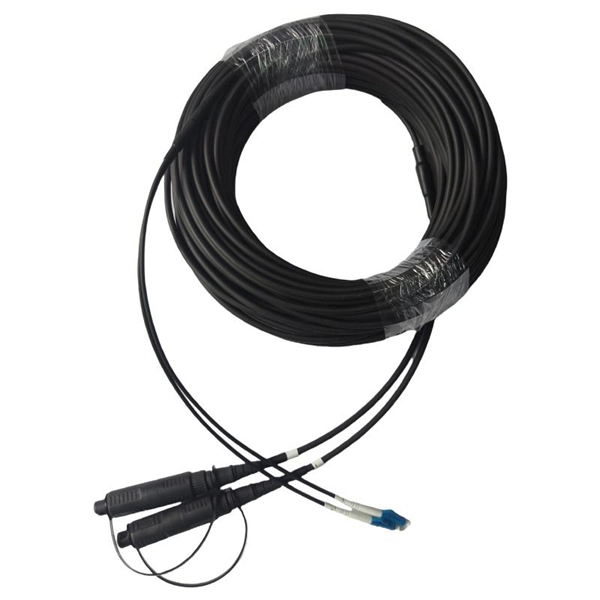
This beginner-friendly guide will walk you through the step-by-step process of fiber optic cable installation for each method, highlighting best practices, tools, and considerations. Proper connection of fiber optic cables is essential to harness these benefits fully, as even minor errors can lead to significant performance issues like signal loss. This article will guide you through the necessary tools, materials, and methods on how to connect fiber optic cables effectively. Starting with site surveys and permissions, to installing fiber optic cable and emphasizing the process as a key stage in mastering fiber optic installation, to the careful handling of cables and high-stakes splicing, each stage is critical. Discover the exact steps, adhere to stringent safety. Single family homes, apartments, condominiums and other multi-dwelling units are increasingly wired with fiber optic cable to future-proof installations and create more reliable, higher-bandwidth and faster speed network and video infrastructures. The processes. Running fiber internally involves extending this high-speed link from the service entry point to a centralized location, such as a dedicated media closet or network rack. This DIY effort is undertaken to maximize performance, improve aesthetics, or relocate the Optical Network Terminal (ONT) to a.
[PDF]

In this article, I'm going to describe how to set up Link Aggregation between two managed switches to provide connectivity, redundancy, and expanded bandwidth. Managed switches provide many advantages for a growing network, including support for VLANs, QoS, and Trunking. I touched on simple VLAN configuration a while back. in the United States and in other countries. App Store and the Apple logo are trademarks of Apple Inc., registered in the U. Google Play and the Google Play. Link Aggregation in UniFi allows you to combine two or more ethernet ports into one. The NVR is connect via Fibre to the USW as well. So. ? Any hints welcome! Archived post. New comments cannot be posted and votes cannot be cast. Imagine transforming multiple network cables into one giant, super-speed "data highway. " That's exactly what link aggregation does. It combines multiple Ethernet connections into a single logical connection, boosting speed, enhancing. Thank you for purchasing the Ubiquiti Networks® EdgeSwitch® XG. This Quick Start Guide is designed to guide you through installation and also includes warranty terms. TERMS OF USE: All Ethernet cabling runs must use CAT6A (or above). It is the professional installer's responsibility to follow local.
[PDF]
MRG specializes in the manufacture of complex electrical distribution and wiring solutions, including electro-mechanical assemblies, wire harnesses, battery cables, and complete box builds. ATEK Distribution supplies professional-grade electrical boxes for residential, commercial, industrial, and government projects nationwide. As a certified SDVOSB with 28+ years of experience, we carry every box type you need — correctly specified, fully documented, and ready to ship. Email Us! Have a question? We're here to help. <meta name="description" content="Serving Southern California since 1953, Walters Wholesale Electric provides electrical supplies, lighting, tools, and gear for contractors and construction professionals. Visit our 25+. Click here for more information (For after-hours use. There will be an additional charge for using this service. ) We are a competitively-priced industrial electrical distributor supplier offering the highest quality products to the electrical wholesale market. Follow us on social media! © 2024 The Ericson Manufacturing Co. | Privacy. Try our Interactive System Diagrams. Learn More From Panel to Plug Lex has you covered. Find helpful conversion charts, documentation, and more. Feedback? Contact webmaster@lexproducts. com LEX Products is a leading manufacturer of power.
[PDF]

Fiber optic cables offer superior performance compared to copper cables, especially over long distances. They provide higher data transmission rates, larger bandwidths and are immune to electromagnetic interference. Fiber optic cables and copper wires are the two primary types of cables used in networks. Fiber optic cables transmit data using light waves, enabling higher. Fiber optic tends to be the more premium solution, while copper wiring is far more common, but why is that? What are the differences between these two cable types, and why might you want to pick one over the other? Here's everything you need to know about fiber vs. Copper wire is more susceptible to interference and has limited data capacity, making optical fiber the preferred choice for modern high-speed. If you're deciding between copper and fiber optic cables, it's not just a question of cost, it's about purpose, environment, and future readiness. Both have distinct strengths that can serve very different networking needs depending on your setup. Fiber optic cables provide. In today's fast-paced digital world, choosing the right network cable can significantly impact the performance, reliability, and security of your communications infrastructure. Among the most commonly used cables are copper and fiber optic cables, each offering unique advantages depending on the.
[PDF]

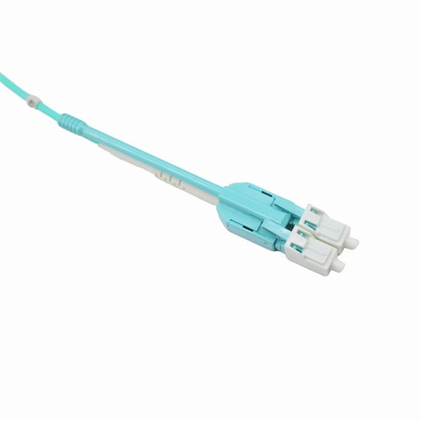
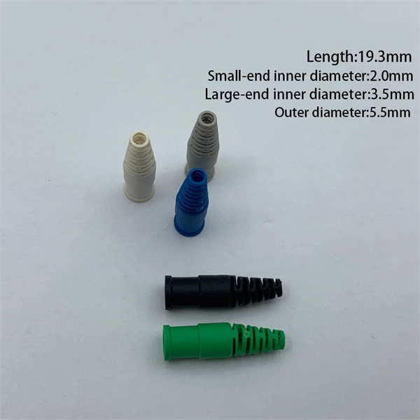
The terminal box provides: Strain relief: Cable clamps and grommets transfer tensile loads from fiber to chassis, preventing microbends and fiber breakage. Bend-radius control: Internal routing with ≥30 mm radius (typical for G. A2/B3 bend-insensitive fibers) minimizes induced attenuation. Slack. A Fiber Access Terminal (FAT), also known as a Fiber Access Terminal Box (ATB) or Fiber Distribution Terminal (FDT), is a key component found in optimized fiber optic access networks for FTTH implementations. It is a small enclosure that can house and protect the fiber optic cables, splices, and connectors. The fiber termination box. GAO Tek's fiber terminal boxes are devices used in fiber optic networks to terminate and manage fiber optic cables. Our boxes serve as a connection point for incoming and outgoing cables, providing cable termination, organization, and protection. GAO's box includes features such as cable. Fiber optic terminal box is a product use for different scenarios in FTTH construction, such as primary or secondary splitting. People usually use it to connect patch cables from the splitter to the indoor cables, meeting the demands for high-speed bandwidth services. It is widely used in optical fiber communication systems, such as Fiber to the Home (FTTH), Local.
[PDF]
Find the Latest Global Communication Tower tenders online with TendersOnTime. Advertisement for Request for Qualifications (RFQ) Department of General Services Real Estate Services Division Project Management and Development Branch RESD-PMDB 2024-16 CONSTRUCTION MANAGEMENT SERVICES COMMUNICATION TOWER PROGRAM VARIOUS LOCATIONS, STATEWIDE Construction Management Services as. Statewide program seeking a qualified firm to replace telecommunications infrastructure with new towers, radio vaults, and supporting infrastructure across California. Our platform offers unrestricted access to eProcurement notices, eTenders, Tender results, and corrigendum updates from 600,000+ government and private tender websites, eProcurement Portals and newspapers from around the. Department of General Services Real Estate Services Division Project Management and Development Branch The Department of General Services (DGS), Real Estate Services Division (RESD), Project Management and Development Branch (PMDB) is requesting Statements of Qualifications (SOQ) from Construction. Are you searching for the latest Communication Tower Tenders from trusted sources across the globe? Tender Impulse is the go-to tender website for businesses seeking verified and timely updates on public tenders, government tenders, and business tenders in a wide range of sectors. With our smart.
[PDF]
Modern fiber-optic communication systems generally include optical transmitters that convert electrical signals into optical signals, optical fiber cables to carry the signal, optical amplifiers, and optical receivers to convert the signal back into an electrical signal. The information transmitted is typically digital information generated by computers or telephone systems. Transmitters The most commo. OverviewFiber-optic communication is a form of for from one place to another by sending pulses of or through an. The light is a form of. First developed in the 1970s, fiber-optics have revolutionized the industry and have played a major role in the advent of the. Because of its advantages over electrical transmission, optical fiber. is used by telecommunications companies to transmit telephone signals, Internet communication and cable television signals. It is also used in other industries, including medical, defense, governmen.
[PDF]

We will look at how to interpret PLC LED status indicators for digital inputs and outputs and how to perform troubleshooting tests using a Digital Multimeter. This section includes the block diagram of the DI 16x24VDC ST module with the terminal assignments for a 1-wire connection. Information on wiring the BaseUnit can be found in the system manual ET 200SP distributed I/O system. The load group of the module must begin with a light-colored BaseUnit. How to wire real-world signals into the Logo's digital inputs to detect whether a machine is running. Covers stack lights, door sensors, relay contacts, and proximity switches — with a complete wire diagram and step-by-step instructions for both electrical engineers and IT teams. You have a Siemens. PLC and DCS control systems Wiring Diagrams for Digital Input (DI), Digital Output (DO), Analog Input (AI), and Analog Output (AO) signals. be responsible or liable for indirect or consequential damages resulting from the use or application of this equipment. The examples and diagrams in this manual are included solely for illustrative purposes. Because of the many variables and requirements. This manual contains information that is necessary to use the NX-series Digital I/O Unit. PLC programs rarely cause failures, so in this article, we'll assume that there are no program errors and that the fault originates in the.
[PDF]