
The procedures in this document describe basic inspection techniques and processes of cleaning for fiber optic cables, bulkheads, and adapters used in fiber optic connections. Note: This document is intended for use by service personnel, field service technicians, and. There are three main principles that needs to be taken in consideration for an efficient optical connection: a perfect core alignment, perfect physical contact and dirt-free connectors. It is important that every fiber connector be inspected and cleaned prior to mating. That advice is misguided. It could hurt an installer or get them sued by an irate network owner. This guide outlines best practices for maintaining and inspecting installed fiber optic infrastructure, enabling network owners to keep their systems running at peak efficiency. Fiber optics infrastructure consists of optical fiber cables, connectors, splice enclosures, distribution panels, and. Small oil micro-deposits and dust particles on fiber optic cable optical surfaces may cause a loss of light or degraded signal power which may ultimately cause intermittent problems in the optical connection. Fiber optic testing and maintenance protocols not only maintain the reliability of the network, but also allow for early detection of potential failures and optimization of performance.
[PDF]
Our cable tray offers efficient airflow, superior corrosion resistance, easy installation, and customisable accessories. Contact us today for a quote or order. Browse our range of Cable Trays. Buy Cable Management Cable Tray, Wire Tray & Cable Baskets. The perfect cable management solution. Shop Today!. Cable Trays PERFORATED METAL CABLE TRAY - LIGHT DUTY (LCT) STRAIGHT CABLE TRAYS Please complete and submit. We'll respond to your product enquiry asap!. Ready To Start Working With Us?. Anything in excess of 2m requires a truck delivery. Fees will be calculated at check out. Products may be returned within 7 days of purchase, provided they are unused, in their original packaging, and accompanied. At Advanced Strut, we specialise in providing high-quality metal cable trays designed for the efficient support of all cable and pipe installations. Our comprehensive range includes both cable ladders and trays, catering to a variety of industrial and commercial needs. With our durable and reliable. 200MM X 50MM 50/100 WIRE MESH CABLE TRAY - 3 METERS at your No. 1 Electrical Suppliers - Best Prices and Fast, Reliable Delivery. Shop Online and Save Now!.
[PDF]

It involves encapsulating the optical chip in a metal box filled with inert gas (usually helium) to protect the optical elements from external environmental influences and enhance heat dissipation. COB, BOX, and TO-CAN packaging each offer unique advantages tailored to specific applications. COB packaging integrates components directly onto a PCB, enabling miniaturization and cost efficiency. BOX packaging seals optical chips in a metal enclosure with inert gas, ensuring long-term stability. The COB process refers to a technology that directly mounts bare chips onto a printed circuit board (PCB), connects them via gold wire bonding, and then encapsulates and protects the chips and wires using organic adhesive. Compared with conventional processes, the COB process offers high packaging. Box, COB, and TO can are currently the most prevalent packaging forms for optical components. Box packaging, also known as hermetic sealing, has a long history. Common optical device packaging methods include COB (chip-on-board packaging), BOX and coaxial packaging. What is COB technology? COB (Chip on board) is a form of packaging that directly bonds the. The invention provides an SFP28 SR optical module structure of a COB process, and belongs to the field of optical module structures. The micro-optical module comprises a shell, an unlocking mechanism, an EMI shielding structure, a circuit board, a micro-optical module arranged at one end of the.
[PDF]
Find and discover Cable Tray manufacturers and suppliers for all products in Jamaica, featuring details on their shipment activities, trade volumes, trading partners, and more. Brilltech Engineers Pvt. brings the Cable Trays in Jamaica just for you! We, one of the well-known Cable Trays Manufacturers in Jamaica, offer top-notch trays that keep your electrical system organized and protected. We have an in-house manufacturing unit where we design products with utmost precision. We use cut-edge tools and. Ready to bring your vision to life? Contact me today, and let's create something amazing together!. Looking to buy a Cable Tray in Jamaica? Jeetmull Jaichandlall (P) Ltd. We believe in building fruitful business partnerships. Every buyer chooses us first because of our. Started back in 1983, Cable House is a recognized name engaged in manufacturing and supplying wide range including Hose Clamps, Cable Ties, Crimping Tools, Cable Tray, Industrial Connectors and more, to the national as well as the international market. With our manufacturing expertise, we have even. As the leading distributor of building materials in Jamaica and provider of other construction services, we are dedicated to delivering strong customer service at world class efficiency and to making a significant contribution to the development of Jamaica.
[PDF]

The complete process for terminating cable runs at a patch panel, from mounting and cable management to punch-down, labeling, and testing every port. To wire a patch panel: Mount the panel in your rack. If you're still deciding which panel style fits your site (keystone vs punch‑down vs pass‑through), start with How to choose a patch panel and come back here once the hardware is locked in. 60-second answer If you want reliable results, the winning recipe is simple: keep pair twists tight right up. Network patch panel, cable manager, network cable, wire stripper, crimping tool, zip ties. Use a small yellow tool or wire stripper to remove the outer jacket of the network cable. Cut off the cross-shaped skeleton of the Cat6 patch cord. Insert. Patch panels make cable management and network organization very easy over long periods of time, but you'll need to wire the panels in order to put them into your network. Not to worry, this guide will walk you through the whole process. Before you jump into the task, ensure that you have the. Testing a patch panel is an essential task to ensure the reliability and efficiency of a network infrastructure. The process verifies the end-to-end connection, ensuring the cable is properly terminated at the wall jack and at the distribution point, such as a switch or patch panel.
[PDF]
Based on the requirement of relevant standards, this paper discusses automatic testing exploratory research, by analyzing the principal experimental objects and information transmission mode of the distribution automation terminal, which adopts IEC-60870-5-104 protocol. The Distribution Terminal Unit (DTU) is a core terminal device designed specifically for modern smart distribution networks. Essentially, it is an intelligent device that integrates data collection, processing, transmission, and control functions. As an important component of the distribution. In this paper, the intelligent industrial automatic technology is used to detect the malfunction indicators and distribution terminals to improve detection efficiency. The system is. This article introduces a case of 35kV ring main unit busbar insulation breakdown failure, analyzes the failure causes and proposes solutions , providing reference for the construction and operation of new energy power stations. On this basis, this paper. Distribution Automation Terminals are an important part of distribution automation systems to deliver real-time monitoring, fault detection, fault location, isolation and power restoration in non-fault areas on multi-line systems. The tester host includes a tester slot in which a USB type wireless network module is inserted. The tester host conducts data.
[PDF]

The PV combiner box test in solar power systems is a fundamental procedure that verifies the accuracy of string connections and the electrical current flowing to inverters. This test helps prevent energy losses while optimizing system performance. ance cables by combining strings at the array locat ciency, reliability and safety in solar energy systems. They enable centralized management in large-scale and remote installation ity), equipment aging, and poor installation practices. MapperX performs this critical test professionally. This guide provides a step-by-step method for safely testing energized PV strings to locate intermittent ground faults using reliable tools and procedures. What Is an Intermittent Ground Fault? An intermittent ground fault is a temporary electrical connection between a current-carrying conductor. A PV combiner box, often referred to as a solar combiner box, is a critical component in solar energy systems. This device plays a significant role in both residential and commercial solar installations, particularly when. We do a lot of solar PV and renewable energy asset inspections here at HelioVolta and SolarGrade! Every time we visit a site, we use the SolarGrade platform to guide our workflow and document our findings. Missing/Improper Label Improper labeling can be a risk to personnel and should conform to.
[PDF]
Fiber testing is the process of verifying the performance of optical fiber cabling. This process includes a range of tests and measurements such as insertion loss, optical return loss, and fiber length. It encompass.
[PDF]

Comply with standards: Follow NEC, IEC, or local codes. Use UL/CE-certified parts and record installation details for future inspections. Before powering on, perform visual checks and multimeter tests. Schedule regular maintenance and inspections to ensure long-term reliability. The purpose of this General Order is to establish requirements for electric distribution and transmission facilities (excluding those facilities contained in a substation) regarding inspections in order to ensure safe and high-quality electrical service. Just like travelers need clear pathways and safety protocols, your electrical circuits need proper management to prevent chaos. You must make safety your top priority when working with low voltage distribution boxes. Label everything. Verify the specifications of the power distribution box against project requirements. Ensure all components are present and undamaged. Confirm compliance with local codes and regulations. Select an appropriate installation location with adequate space. Publish Time: 03/08 2025 Author: Site Editor Visit: 918 The installation requirements and specifications of Distribution box involve many aspects, including site selection, fixing method, wiring specifications and safety protection.
[PDF]

This report covers the optical, environmental, and mechanical performance of the LC-UPC, singlemode fiber optic BOAs, provided by Tyco Electronics, Fiber Optics Business Unit. Qualification testing was completed by a third party in July 2004. IDEAL FOR DEBUGGING OPTICAL POWER PERFORMANCE & OPTICAL INSTRUMENT CALIBRATION CORRECION & FIBER SIGNAL ATTENUATION. As optical passive devices, FS attenuators are mainly used in fiber optic to debug optical power performance & optical instrument calibration correction & fiber signal. L-com offers an extensive line of dual wavelength (1310/1550nm) Singlemode fiber optic attenuators. These versatile in-line attenuators are the perfect solution for attenuating Singlemode fiber connectors for both lab and commercial applications. Constructed of the highest quality materials and. zation system's perfo. the power of an optical signal. Our LC/APC single mode attenuators can handle a maximum o 1 watt of optical input power. This device contains one ale and one female LC/APC port. LC/APC optical attenuators can be ordered in attenuation. Fixed loopback type attenuators from OMC offer defined control of optical signals in both integrated and add-on products. Depending on the project or need, fixed attenuators can limit (attenuate) the amount of light passing through to the exact levels your project or application requirement.
[PDF]

The fastest way to test a fluorescent tube is with a multimeter set to continuity mode. Each end of the tube has two pins connected by a thin filament inside the glass. If either filament is broken, the tube is dead. The whole test takes about 30 seconds per tube once you know what. This is a complete guide for testing a fluorescent light bulb with a multimeter. You don't have to be an expert in electrical work. This process measures electrical resistance to determine if the tube has suffered an internal failure before replacing the bulb or investigating the ballast. This guide provides a comprehensive understanding of the process, equipping you with the knowledge and. To test a fluorescent light bulb, observe any of the following: flickering light, low brightness, buzzing sound, delayed start, and fading color and light variation. Turn off the power to the circuit that powers the fixture and keep the leads steady to ensure accurate readings. Multimeters provide. How to Test Light Bulbs & Fluorescent Tubes with a Multimeter (Continuity Check) Is your lamp or fixture failing to light up? Before you buy a new bulb, you need to confirm if the bulb or tube itself is the problem! A simple continuity check using a multimeter can instantly tell you if the filament.
[PDF]

Regularly testing fiber optic cables helps minimize network downtime, lengthens the network's longevity, reduces maintenance requirements, and helps support network reconfiguration and upgrades. Fiber optic testing ensures the performance and reliability of fiber optic networks. Key tests include: Effective fiber testing utilizes advanced tools such as Optical. Fiber optic testing for continuity is crucial in ensuring that light transmits through fiber optic cables without interruptions, safeguarding seamless data transmission. This guide talks about the primary methods and tools for effective continuity testing in fiber optic cable networks. Insertion loss testing confirms whether the cable meets design loss budgets. OTDR testing identifies events along the fiber length, including: OTDR is essential for long-distance FTTH feeder and distribution cables. After the cables are installed and terminated, it's time for testing. For every fiber optic cable plant, you will need to test for continuity, end-to-end loss and then troubleshoot the problems. If it's a long outside plant cable with intermediate splices, you will probably want to verify the. We'll explain why it's vital to test fiber optic cables, the three most popular methods, and when you should use them. Why Testing Fiber Optic Cables Matters? Regular testing of fiber optic cables is not just a preventive measure; it's an.
[PDF]

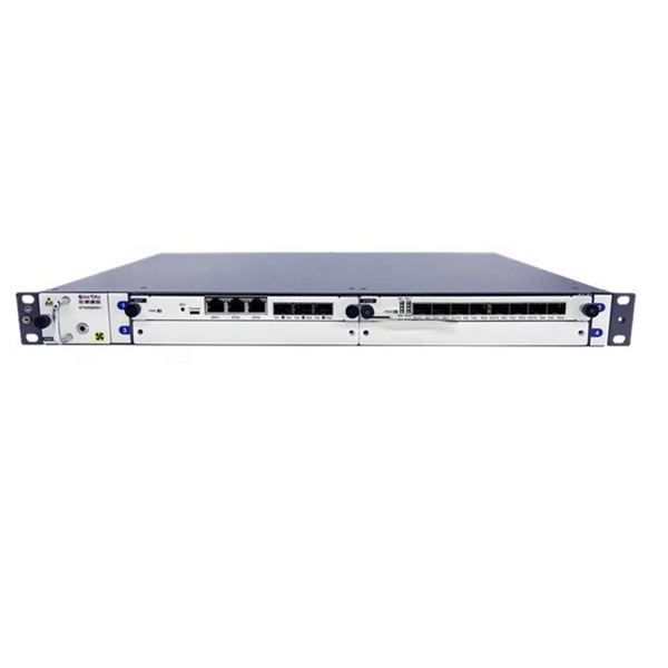
This report lists the top Passive Optical Network (PON) Equipment companies based on the 2023 & 2024 market share reports. Mordor Intelligence expert advisors conducted extensive research and identified these brands to be the leaders in the Passive Optical . Global Outlook – By Component (Optical Power Splitters, Optical Filters, Wavelength Division Multiplexer/De-Multiplexe), By Structure (Ethernet Passive Optical Networks (EPON), Optical Network Terminal (ONT), Optical Line Terminal (OLT), Gigabit Passive Optical Network (GPON), Optical Network. As per MRFR analysis, the Passive Optical LAN Market Size was estimated at 25555. 89 USD Million in 2024. The Passive Optical LAN industry is projected to grow from 28704. 79 USD Million by 2035, exhibiting a compound annual growth rate (CAGR) of 12. Need. Discover the innovators and market leaders driving Passive Optical Network technology into a new era. Get expert insights into competitive positioning, market trends, and strategic imperatives for stakeholders. For a deep-dive analysis with in-depth forecasts, download the Passive Optical Network. The global passive optical network (PON) market size was valued at USD 17. 80% during the forecast period. 9% from 2024 to 2030. With the proliferation of bandwidth-intensive applications, such as streaming services, online gaming, and.
[PDF]
