This test station do the auto-testing on 12 core (24 core) for insertion loss and return loss, highly efficient multi-core fiber insertion and return loss measurement and make high precision on the measurement result with OTDR mandrel free technical adopting. (MPO/MTP) mandrel free insertion loss test station is specially design for multi fiber testing. It combines three. •Compact benchtop instrument for all-in-one operation optic components quickly and accurately. The system has a or LED source for multi-mode applications. With a dual two wavelengths in less than 1 second. ILM-100 system comes integration into test systems. the measurement result with OTDR mandrel free technical adopting. Automatically complete the 12-core (24-core) dual-wavelength IL&RL test. The application of OTDR winding-free technology has greatly improved the insertion. You can make an inquiry about this product. Your e-mail will not be leaked.
[PDF]

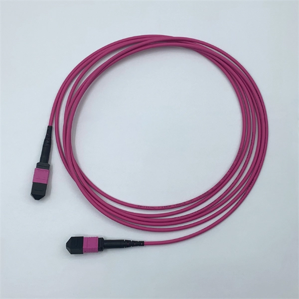
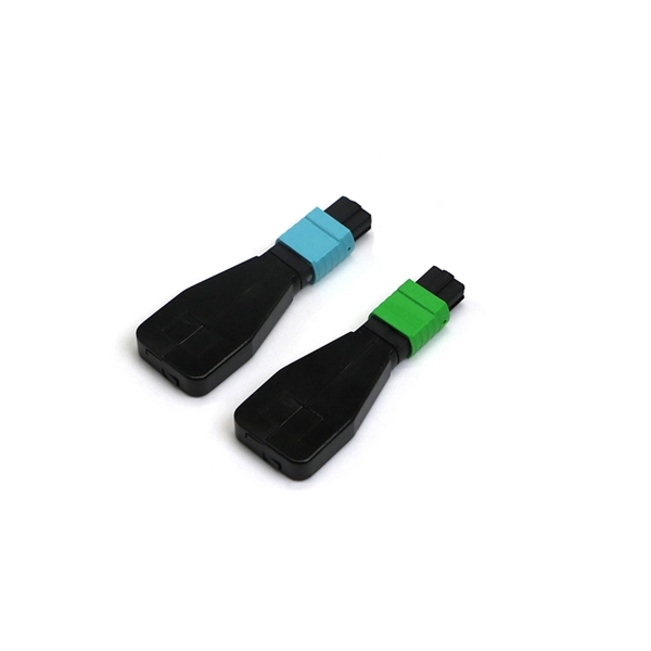
FiberMall MPO16 APC Y Splitter Cables 10m are designed for 800G QSFP-DD/OSFP DR8/OSFP XDR8 optics direct connection and support 800G transmission for Hyperscale Data Centers. Multimode PLC Splitter is a passive optical device used to split incoming signals into two or more output signals. They're capable of operating over a broad wavelength range from 650 nm to 1350 nm (Typ. 650nm, 850nm and 1300/1310nm). 5/125 (OM1, OM2, OM3 and. High-Quality Construction: This Fiber Optic PLC Splitter is manufactured by UT-KING, a reputable brand known for its reliable products, ensuring a durable and long-lasting performance. Optimized for FTTH Solutions: Designed for use in Fiber-to-the-Home (FTTH) applications, this 1x2 OM3 PLC Splitter. Optical coupler is an optical device that combines or splits power from optical fibers. Note: All insertion loss and insertion loss referenced without connectors. Takfly, established in 2000, has been manufacturing. Optional split ration 1:99, 2:98, 5:95, 10:90, 20:80. USource OM3 Fiber Coupler is a 1x2 or 1x3 passvie optical multimode splitter based on FBT (Fused Biconic Taper) technology, packaged in mini ABS box module or steel tube, split into different rations 1:99, 2:98, 50:50, 10:90, 20:80.
[PDF]
United Rentals has low-pressure air testing equipment for rent, most commonly used to test for line acceptance or leaks in pipe joints and sewer line installation. For more. Air Testers install blower door testing equipment (big fans) to an external opening (typically a doorway) and will use this to pressurise or depressurises the building and test over pressure differentials Using thermal imaging, the tester will be able to identify air leakage points where warm air. Simple to Operate: The air ejector has no moving parts and no lubrication is necessary. After applying leak detection fluid along the seam, simply place the vacuum device over the area to be detected and open the air valve. Rugged Yet Lightweight: Our shockproof Vacuum Devices are built with. A pioneering approach to fabric air permeability measurement that releases a low-pressure pulse of air for realistic and accurate measurement of airtightness of buildings in seconds. A portable diagnostics fan that can help identify air leakage paths within buildings, helping to minimise. This is where you can browse products in this store. For more information, visit our resource. Airtightness tester s help make homes use less electricity by finding where air leaks are. When structures are less leaky, they need lower utility bills to heat or cool them. This savings makes buildings more environmentally friendly. By sealing tightly, pollution from outside cannot easily enter.
[PDF]
Run the loopback-detect untagged mac-address ffff-ffff-ffff command in the system view to broadcast BPDUs for loopback detection and prevent them from being terminated by unexpected devices. Huawei's comprehensive portfolio of products and solutions enables you to realize smooth digital transformation and rapid growth of virtualization, Big Data, and cloud services. Huawei switches already help customers achieve success in industries such as finance, Internet, retail, education. Plan the network configurations, configure loop prevention protocols, and enable loopback detection to prevent loops. They provide ultra-high-density 10GE/40GE/100GE/200GE/400GE full-rate access ports, meeting customers' requirements for quickly building campus networks with a simplified. CloudEngine S12700H series switches are Huawei's next-generation modular core/aggregation switches designed for high-end campus networks in the all-wireless era of Wi-Fi 6/7. CloudEngine S12700H series switches come in two models, which offer four and eight LPU slots, respectively. The S9700 uses an advanced multilayer switching architecture to support sustained bandwidth upgrading and to provide 40GE. This document provides campus networks typical configuration examples and feature typical configuration examples. "Campus Networks Typical Configuration Examples" provides typical campus network networking modes and a variety of deployment examples.
[PDF]

Wiring an electrical panel box can seem like a daunting task, but with the right knowledge and tools, it can be done successfully. In this guide, we will provide you with a step-by-step process to help you wire an electrical panel box safely and efficiently. Distribution Board or DB is an electricity supply system or a common enclosure that distributes the electrical power feed into subcircuits. It includes isolator, RCCB (Residual current circuit breaker) or RCD (Residual-current device) devices, protective fuses or MCB's (Miniature Circuit Breaker). This book serves as a concise guide for learners interested in basic electrical house wiring concepts. It provides practical instructions for various electrical configurations and connections, emphasizing the importance of safety and proper installation. Additionally, it introduces essential. The Guidelines For Electrical Wiring In Residential Buildings has been prepared as a wiring guide for all Wiremen and Electrical Contractors for undertaking electrical wiring in residential buildings to conform to the Electricity Regulations 1994. The Guidelines are prepared in a concise and. An electrical panel box, also known as a breaker box or a distribution board, is a crucial component of any electrical system. All the electrical sub circuits are originated from a Distribution Board. To understand how a breaker box works, it is helpful to.
[PDF]
In practical applications, there are many electrical connection methods for industrial power distribution boxes, which will be introduced below. Primary distribution systems consist of feeders that deliver power from distribution substations to distribution transformers. Many feeders leave substation in a concrete ducts and are routed to a nearby pole. At this. Proper sub panel wiring is a fundamental skill for any licensed electrician, critical for safely expanding a building's electrical capacity. The process involves installing a secondary breaker panel fed from the main service panel. Key compliance points include performing an accurate panelboard. Four basic circuit arrangements are used for the distribution of electric power: radial, primary selective, secondary selective, and secondary network circuit arrangements. A busbar is a large-section conductive. The Secondary Distribution Box (SDB) receives power from Main Power Distribution box via an extender cable and provides a central power distribution to feed normal branch circuits to the electric floor modules through snap-on extender cables. The SDB can be fitted with terminal blocks for custom. Small electrical installations normally have only one distribution board, connected directly to the main service, and appliances are powered with branch circuits protected by breakers. However, powering all loads from the same distribution board is impractical in larger installations, since the.
[PDF]

First, inspect the optical module appearance for physical damage, cracks, missing components, poor solder joints, or burn marks. Next, compare voltage, resistance, and waveform parameters between a normal it and the suspected faulty one, both in powered and unpowered states. As core components of optical communication systems, the proper installation and use of optical modules directly impacts network stability. This article systematically identifies common anomalies during optical module installation. However, during installation and daily operation, various issues may arise. The following will introduce the causes of various problems and how to deal with them. Optical module method/step 1. During the test, the value of the module I BiasADC is 0, and the TXLOP-ADC and. These compact devices convert electrical signals to optical signals and vice versa, enabling data transmission over fiber optic cables. While generally reliable, failures do occur, leading to frustrating downtime, performance degradation, and costly troubleshooting. This comprehensive guide details. Have you ever dealt with sudden network drops from faulty optical modules? Issues like this cannot only break communications, but they can really jeopardize business continuity.
[PDF]

The max insertion loss of a fiber patch cable is 0. 75 dB (the maximum acceptable value) in the TIA standard. Insertion loss (IL) and return loss (RL) are key performance indicators of fiber optic patch cords. This article explains their concepts, standards, testing methods, and FiberMania's quality assurance workflow to ensure optimal network performance. Fiber optic patch cords are crucial components in. A: Fiber optic loss refers to the reduction in signal strength as it travels through the fiber optic cable. This can be due to various factors, including attenuation, connectors, and splices. Q: How is fiber optic loss measured? A: Fiber optic loss is typically measured using an Optical Loss Test. The estimate, called a "loss budget" is calculated using typical component losses for each part of the cable plant - the fiber, splices and/or connectors. If the measured loss exceed the calculated loss by a significant amount (remembering the inherent uncertainty in all measurements), the system. Insertion loss is usually shortened to IL, and the unit of measurement for insertion loss is dBm. ) in transmission systems. It is the power attenuation of the signal after. At TARLUZ, we specialize in manufacturing high-performance fiber optic patch cords that comply with global industry standards, ensuring optimal signal integrity and long-term stability.
[PDF]
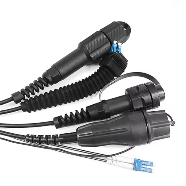
Get the wrong connector type, the wrong polish, or skip proper fusion splicing technique—and you're looking at elevated signal loss, increased back reflection, and a field termination that fails certification. Thoracostomy tubes are indicated for management of air or fluid in the pleural cavity. Pigtail catheters have emerged as an effective and less morbid alternative to traditional large bore chest tubes for evacuation of pleural air or fluid. However, they do not come without complications which. Traditionally large-bore tube thoracostomy has been the standard of care for treating many acute intrathoracic pathologies. However, the advent of less invasive small-bore chest tubes, also known as pigtail catheters, has gradually led to a paradigm shift. They are used to treat a variety of conditions including pneumothorax, pleural effusion, and postoperative evacuation of air and fluid. There are a number of types and sizes of chest tubes available ranging. Return loss is the ratio of signal power injected from a source compared to the amount that is returned or reflected back toward the source. It is a critical performance parameter in both copper twisted pair and fiber optic cabling systems, because it can interfere with the transmitted signal and. Executive Summary: A fiber optic pigtail is one of the most commonly specified yet least understood components in structured cabling.
[PDF]

5 dB depending on splitter type. Common planning value: 0. Optional: patch panels, attenuators, or extra components. Helps cover dirt, aging, and measurement tolerances. Adds Rx power and margin calculation. Calculate insertion loss for passive optical splitters in PON and distribution networks. Power is divided equally among output ports. Excess loss accounts for manufacturing imperfections, typically 0. DISCLAIMER: These calculators are provided for. Optical splitters, encompassing FBT (Fused Biconical Taper) couplers and PLC (Planar Lightwave Circuit) splitters, are prevalent passive optical devices designed to divide fiber optic light into multiple segments based on a specified ratio. Fiber optic splitters are vital components within. In fiber optic networks, particularly in FTTx (Fiber to the x) and PON (Passive Optical Networks) deployments, splitters play a central role in distributing the optical signal from a single source to multiple destinations. Optional: patch. Understanding optical splitter loss isn't just about plugging numbers into a calculator. It's about knowing what factors contribute to that loss, how manufacturers specify it, and how it impacts the overall performance and reach of your network. Understanding the types of splitters, their impact on network performance, and how to measure their losses ensures high-quality network operation and facilitates optimal splitter selection based on.
[PDF]

The typical specification range of return loss of a fiber connector is -15 dB to -60 dB. Return loss is also known as reflection loss. It indicates the amount of signal reflected back to the transmitting end. Return loss refers to the power loss caused by the reflection of part of the signal back to the signal source during transmission due to the discontinuity of the transmission. Insertion loss, also known as attenuation, is the loss of optical power that occurs when light passes through a fiber optic connector. It is caused by factors such as misalignment, air gaps, and imperfections in the connector components. The lower the insertion loss, the better the performance of. Reflectance (which has also been called "back reflection" or optical return loss) of a connection is the amount of light that is reflected back up the fiber toward the source by light reflections off the interface of the polished end surface of the mated connectors and air. It is also called. Insertion Loss (IL) is the amount of optical power lost as the signal travels from one point to another in a fiber optic link, usually across connectors or splices. Formula for. In optical fiber communication, insertion loss and return loss are two important parameters to evaluate the quality of interfaces between some optical fiber components, such as optical fiber connector, fiber patch cable, pigtail fiber, etc. While it's natural to have.
[PDF]
A fiber optic pigtail is a short length of optical fiber —typically 0. 5m to 2m—that has a factory-terminated connector on one end and bare fiber on the other end. The connector end is polished and tested under factory conditions, ensuring low insertion loss and high return loss. They are the bridge between fiber optic cables in the field and the equipment or patch panels that manage them. By combining factory-installed connectors with spliced bare fiber, pigtails ensure that network installers can create. The most urgent stage of the process is, in fact, separating fiber optic pigtail, also known as pigtail fiber or pigtail fiber optic cable. These short, pre-terminated cables play a vital role in terminating and splicing optical fibers, especially in complex fiber infrastructure such as data. Executive Summary: A fiber optic pigtail is one of the most commonly specified yet least understood components in structured cabling. Get the wrong connector type, the wrong polish, or skip proper fusion splicing technique—and you're looking at elevated signal loss, increased back reflection, and a. A fiber pigtail is a short optical fiber cable with a connector pre-installed on one end and a bare fiber on the other. The quality and.
[PDF]

Optical return loss is the amount of light that is reflected back to the source, this reflected light is measured at each connector and splice at each point over the entire fiber link. This is always measured in dB (decibels) and will be displayed as a negative number. The closer the number is to. The polish of a singlemode fiber endface plays a significant role in reflectance. Understand what you need before you specify. The Institute of Electrical and Building the ORL story Electronics Engineers (IEEE) recently Within a fiber-optic channel or path-released new specifications within way. Optical Return Loss (ORL) in fiber optics refers to the amount of light that is reflected back toward the source in a fiber link. ORL is usually expressed in decibels (dB) as a positive value, with. Return loss (RL) is also called reflection loss. When high-speed signals enter or exit a part of an optical fiber, such as an optical fiber connector, discontinuity and impedance mismatch may cause reflection, which is the return loss of an optical fiber. Poor ORL is commonly caused by dirty connectors, poor splices, mismatched connector types, or damaged fibers. ORL is measured using ORL meters. Home Coherent Optics Optical Return Loss (ORL) Explained Comprehensive Guide to Understanding and Managing Back-Reflections in Fiber Optic Systems What is Optical Return Loss (ORL)? Optical Return Loss (ORL) is a critical parameter in fiber optic systems that quantifies the amount of light.
[PDF]
GPON Xpert is a modular tool designed for R&D, laboratory and field application engineers engaged in the development, testing and deployment of G-PON standard-compliant solutions. The GPON Xpert multi-layer analyzer is a unique protocol analyzer for G-PON products. GPON Xpert verifies the. Fiber Optical Test offers a comprehensive line of PON-specific testing solutions designed for fiber network installation, activation, and maintenance. Passive Optical Networks (PON) demand precise testing technologies tailored to their unique architecture and performance requirements. Fiber Optical. OLP-88 TruePON tester is an innovative tool using GPON data analysis technology. It is the ideal test unit for field technicians dealing with GPON network service activation and for support teams in charge of resolving service complaints and identifying the sources of issues. GPON Xpert verifies the. TraceSpan's non-intrusive solutions empower broadband access networking with deep protocol analysis across all communication layers Gain complete visibility and deep understanding of your access network elements and the traffic running through them, powered by independent testing tools and.
[PDF]

Select the correct wavelength and set your reference. You measure optical power in dBm or insertion loss in dB. Consistent procedures ensure accuracy. Measure total signal loss from fiber, connectors, or splices. Optical fiber attenuation is the attenuation per unit length of optical fiber, and the unit is dB/km. When connecting two optical fibers, there will be loss inside any connector or joint. Consistent measurement techniques. While optical power meters are the primary power measurement instrument, optical loss test sets (OLTSs) and optical time domain reflectometers (OTDRs) also measure power in testing loss. TIA standard test FOTP-95 covers the measurement of optical power. Optical power is based on the heating power. Light Source: The CMA5 Series Light Sources provide an economical and stable laser source for use in point-to-point attenuation measurement. They feature a rugged design, built to withstand the difficult testing environment of fiber optic cable installation and maintenance. The CMA5 Light Sources. When talking about optical measurements, wavelength basically means how far a wave pattern repeats itself, usually measured in nanometers (nm). Commonly, a power meter on its own is used to measure absolute.
[PDF]
