
If the optical module is faulty, replace it with the spare part. If the fault is caused by the configuration or environment, advise the customer to optimize the configuration or environment. This section describes how to enable or disable the optical module laser. Before locating or troubleshooting a link failure, maintenance engineers should ensure that the optical module laser is disabled so that it cannot cause injury. The optical module can be configured to disable the laser. Huawei switches will authenticate the access optical module, and when the access module is verified to be non-Huawei original, a large number of alarm messages will pop up in the default state; at the same time, Huawei also provides commands to turn off the alarms of non-Huawei data center. Huawei switches perform authentication on inserted optical modules. By default, numerous alarm messages will be generated when a non-original Huawei module is used. Huawei provides dedicated commands to disable alarms triggered by uncertified optical modules on its data center switches. Taking the. An optical module is not completely installed in position. Huawei S5720-32P-EI-AC Switch II.
[PDF]

Run the following command to view detailed optical module information on the device interface: display transceiver interface <interface-type> <interface-number> verbose The command output is divided into two parts:. Run the following command to view detailed optical module information on the device interface: display transceiver interface <interface-type> <interface-number> verbose The command output is divided into two parts:. When the optical module on an interface is faulty, you can run the display commands to view information about the optical module. Related Information Video Identify a Huawei-Certified Optical Module Run the display transceiver [ interface interface-type interface-number | slot slot-id ] [ verbose ]. During use, reading optical module information helps understand its real-time operating status, enabling faster troubleshooting of link abnormalities. The following uses the Moduletek SFP-10G-LR module connected to a Huawei S6700 switch as an example to introduce how to read information of the. See the interface module via the optical display command information, including general information of the optical module, manufacturing information, and alarm information. If it is not a Huawei-certified optical module, replace it with a Huawei-certified optical module. If the optical module is installed on a GE port, run the display interfaceGigabitEthernet x/x/x command to view port information when the optical module.
[PDF]
If the optical module is faulty, replace it. If the fault is caused by incorrect configuration or networking environment, change the configuration or networking environment. If the fault persists, contact technical support personnel. Check whether the optical modules are. port is disconnected due to optical module faulty (0xF0060004) on port is disconnected. Config log : As the port is disconnected from the application server or other devices. If the optical module is not completely installed in position and the latch boss is not secured, the device cannot identify the optical module. Solution: To solve this problem, you can follow these steps: Check if the fiber and optical modules are compatible. Perform a. Optical modules are widely used in switches, network interface cards (NICs), routers, and other communication devices. During use, reading optical module information helps understand its real-time operating status, enabling faster troubleshooting of link abnormalities. Indicates the MIB object ID of the alarm. See the. If it is not a Huawei-certified optical module, replace it with a Huawei-certified optical module.
[PDF]

Bit Error Rate (BER) is a critical performance metric in optical communications that measures the number of errors occurring in a transmitted data stream over a certain period. It is defined as the ratio of the number of bits received in error to the total number of bits transmitted. This ratio is most often expressed using scientific notation (e., 10⁻⁸. USI has industry-leading capabilities in high-speed signal integrity and power integrity (SI/PI) design, as well as advanced thermal simulation and optical simulation using Zemax. In addition, we have strong expertise in high-speed PCB design utilizing mSAP and substrate PCB technologies. USI also. Unlock AI-driven, actionable R&D insights for your next breakthrough. As optical links are increasingly used for high-speed data. Even a digital data transmission system is not totally error-free — statistical fluctuations related to noise influences cause a small percentage of the transmitted bits to be corrupted. The average fraction of incorrectly transmitted bits is called the bit error rate. Offers precise, cost-efficient optoelectronic signal and anomaly testing for high-speed transceivers. · Use control board and replaceable.
[PDF]

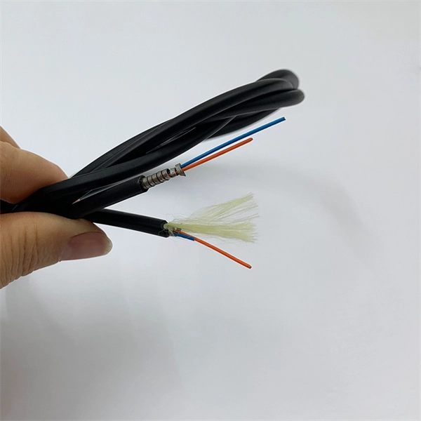
Its typical transmission distance is 20km or 40km. For instance, some ethernet switch manufacturers refer to the 1000BASE-LH SFP as the 1G 1310nm 40km SFP transceiver, which indicates the module's transmission distance and wavelength. The 10G SFP+ dual-fiber optical module is a small pluggable optical transceiver that adopts a dual-fiber bidirectional design. It completes signal transmission (Tx) and reception (Rx) through two independent optical fibers, ensuring the stability and reliability of signal transmission. An SFP (Small Form-factor Pluggable) module transmits data over fiber using specific wavelengths and power levels, which directly influence how far the signal can travel before degradation occurs. This is why two. If the optical module works at a wavelength near 850nm (880nm) or 910nm (940nm), then the module is a multi-mode fiber (MMF) optical transceiver, and if the working wavelength is 1310nm or 1550nm, it is a single-mode fiber (SMF)optical module. Generally, the maximum transmission distance(generally. The transmission distance of optical transceiver modules is divided into short distance, medium distance, and long distance. A 1-core module uses a single fiber core for data transmission, while a 2-core module uses two cores. o Think of a highway. Chromatic dispersion This is a key factor affecting single mode fiber distance.
[PDF]
The LS-SM3101-20C SFP transceivers are high performance, cost effective modules supporting data rate of 125Mbps/155Mbps and 20km transmission distance with SMF. The transceiver consists of three sections: a Cooled EML laser transmitter, a APD photodiode integrated with a trans-impedance preamplifier (TIA). The AFCT-5745NPZ/UPZ Lead-free Singlemode Optical Transceivers have been qualified in accordance to the requirement of Telcordia Document GR-468-CORE under the supervision of Avago Technologies Quality & Reliabil-ity Department. This report summarizes the qualification tests over a range of. Copyright © 2022 GOC-UZ. See our terms of use and privacy policy. Volza's Solution gives you 100x return in Six Months! Use strategic filters to explore Optical transceiver module Import data like a seasoned analyst, uncovering hidden opportunities in the Optical transceiver module import business. Our database includes 321 Import shipments, involving 63 Buyers. Up to now, MEISU has developed various high-temperature resistant optical devices not only with regular SM fiber, but also with PM fiber array by applying special high-temperature coating to the normal PM fiber, providing muiltiple choices for silicon photonic (SiPh) solder reflowable assembly at.
[PDF]

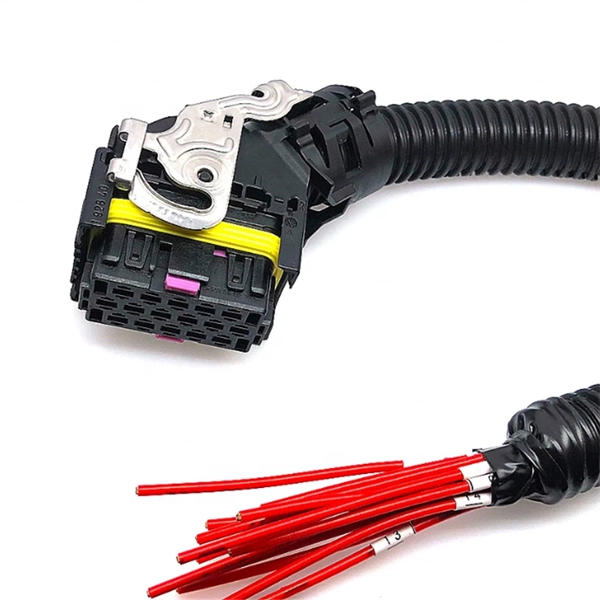
Run the display transceiver [ interface interface-type interface-number | slot slot-id ] [ verbose ] command to view information about the optical module on a specified interface. In optical communication equipment, an optical module (Optical Module) contains several types of semiconductor chips that work together to complete the transmission and processing of optical signals. These chips typically include laser chips, photodetector chips, driver chips, transimpedance. When the optical module on an interface is faulty, you can run the display commands to view information about the optical module. Today, we will deeply analyze the four mainstream models of 100G QSFP28 dual-fiber optical modules: QSFP28-100G-SR4, QSFP28-100G-LR4, QSFP28-100G-ER4 and. The following uses the Moduletek SFP-10G-LR module connected to a Huawei S6700 switch as an example to introduce how to read information of the connected optical module on a Huawei switch. Figure 1 Schematic Diagram of Optical Module Connected to Switch 1. Optical Module Status Check Run the. Upgrade to 100G or 400G optics and save. Cisco Transceiver Modules - Learn product details such as features and benefits, as well as hardware and software specifications. Network administrators have a major challenge determining the right Cisco SFP modules, understanding complex model numbers that directly affect network performance and stability.
[PDF]

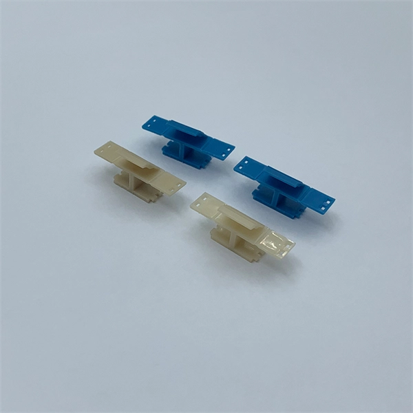
The optical module is usually composed of Transmitter Optical Subassembly (TOSA, containing a laser LD Chip), Receiver Optical Subassembly (ROSA, containing a photodetector PD Chip), a driving circuit, and an optical and electrical interface. Its schematic is shown in. This section explains the structure of a typical pigtail butterfly module, which gets its name from the two rows of seven leads at right angles on each side of the metal package plus an optical fiber pigtail at one end (Fig. Let's look at the internal structure (Fig. 2) of a common butterfly. Optical modules are devices used to connect network devices, transmit and receive data between network devices, and can be used to convert optical and electrical signals. The optical module is a very important component in an optical communication system. Optical devices are the core components of optical modules. TOSA and ROSA in Common Optical Transceiver Modules For ordinary optical transceiver modules, there are two optical devices, TOSA and ROSA, which have opposite effects.
[PDF]

A constant trend in optical modules is to offer higher data rates within the size-limited and thermally-limited form factor by using smaller, integrated Power and Data-Converter solutions. The SFP module is a hot-pluggable optical transceiver used for connecting network switches. It converts electrical signals to optical signals and vice versa. For the 1G SFP module, it is primarily divided into the following two categories: Optical SFP Transceiver Optical transceiver connection RJ45. The optical module serves as a crucial component in optical fiber communication systems, operating at the physical layer, which is the lowest layer in the OSI model. An. Optical modules and media converters are both key photoelectric conversion devices widely used in fiber optic communication, data centers, enterprise networks, and broadband access systems. Many users are confused about their roles, differences, and connection rules. This article will clarify. Microwave photonics technology (MWP), which has been applied to various radar, Telcom, Electronic Warfare systems, is now facing more and more challenging development trend of miniaturization and modular array for increasing node counts and system complexity.
[PDF]
A fiber loopback module is a compact diagnostic tool that allows engineers to verify whether an optical port is functioning properly. By looping the transmitted signal (Tx) directly back to the receiving end (Rx), it enables a closed test without requiring a live network connection. This is where the fiber loopback module comes in. Correct fiber count, gender, polarity, and internal lane mapping matter more than simple connector fit. For procurement, the real selection threshold. This article explores the critical role of MPO/MTP loopbacks in testing high-density fiber optic networks, such as 40G and 100G systems. It details the internal mechanics of signal redirection, the importance of polarity mapping, and how these tools are used to troubleshoot transceivers and verify. MPO loopback modules are passive assemblies used to send optical signals back to receiving lanes for port verification, diagnostics, and simulation. In as much as this guide explains the primary use of the MPO loopback connector, it also covers its operation. What is a Duplex LC Fiber Loopback Module? A Duplex LC Fiber Loopback Module is a testing tool designed to create a loop in a fiber optic network. It consists of a compact module with two LC (Lucent Connector) ports, capable of connecting two optical fibers. The module “loops” the signal sent out.
[PDF]
The optical module serves as a crucial component in optical fiber communication systems, operating at the physical layer, which is the lowest layer in the OSI model. Its primary function is to achieve optoelectronic conversion by converting electrical signals into optical. ity and improved link performance. And now our EDGE8 solution delivers even more value – more applications, more options, more flexibility, more security, and more ways to seamlessly oducts without prior notification. Among various optical module form factors, SFP (Small Form-Factor Pluggable). Optical modules are electronic devices that convert electrical signals into optical signals for transmitting data over an optical fiber. These modules typically consist of a transmitter, which converts electrical signals into a light signal, and a receiver, which converts the received signal back. As an essential component of optical fiber communication, optical modules are optoelectronic devices that facilitate the conversion between optical and electrical signals during the transmission process. An. What is an Optical Module? The Ultimate Guide to Principles, Types, and Troubleshooting Optical Modules (also known as Optical Transceivers) are critical components in fiber optic communication systems.
[PDF]

This quick-reference guide focuses on what to measure, how to interpret results, and what to do when findings indicate marginal performance. Whether you're a network engineer validating new inventory or an integrator preparing for deployment, knowing how to test optical transceiver modules can save time, reduce failures, and ensure SLA compliance. Unchecked optical modules can cause: Testing ensures compliance with IEEE 802. 3 and MSA. This article provides a comprehensive guide on measuring key performance indicators to evaluate the functionality of optical modules, with a specific focus on the sfp28 transceivers. A comprehensive understanding of the working principle of an optical module is essential for determining the. Evaluating the performance of optical modules is a practical discipline: you must verify optical power and signal quality, confirm electrical/optical compliance, validate link-level behavior under real traffic, and document results in a way that supports reliability engineering. This. The optical module serves as a crucial component in optical fiber communication systems, operating at the physical layer, which is the lowest layer in the OSI model. Its primary function is to achieve optoelectronic conversion by converting electrical signals into optical signals and vice versa.
[PDF]
The SFP-10G-ER transceiver module is the proven, standards-based workhorse for extending 10 Gigabit Ethernet up to 40km over cost-effective single-mode fiber. This hot-pluggable SFP+ transceiver is engineered to transmit 10Gbps data streams over single-mode fiber (SMF) for link lengths up to 40 kilometers, making it indispensable for metro Ethernet, campus backbone networks, enterprise data center interconnects (DCIs), and telecom access networks. 10GBASE-LR SFP+ Module: 10Gb/s data rate, Single-Mode, duplex LC connector, 1310nm wavelength, the transmission distance up to 10km, working temperature: 0℃ ~ 70℃, Tx Power (dBm): -6. Equipped with an LC connector. Experience reliable high-speed networking with the VIVOTEK SFP-2000-SM13-10, a 10 Gigabit Mini GBIC designed for enhanced performance. Utilizing 10GBase-X technology, it delivers data transfer speeds up to 10 Gbps over compatible cables, ensuring efficient and scalable connectivity. This module. The 10 Gigabit Singlemode SFP+ Transceivers provide high-performance, reliable connectivity for modern 10 Gigabit Ethernet (10GbE) networks. These transceivers are designed for singlemode fiber, offering superior performance over long distances. Whether you're working on data centers, campus. These SFP transceiver modules come in a metal housing that reduces electromagnetic interference and increases their durability.
[PDF]

One of the core advantages of MPO patch cords is their high-density integration. Traditional patch cords have only 1-2 cores per cord, while MPO patch cords can integrate 12-48 cores, enabling multi-port connections with a single cord. Fiber cores are the heart of fiber optic cables, transmitting light signals that carry data. Made from either high-quality glass or plastic, the core plays a critical role in determining the cable's performance. The total number of cores for a 1pc fiber patch cable is calculated as the number of. Multi-core patch cords are fiber assemblies containing multiple fibers within a single cable jacket, typically available in 4, 6, 12, and 24-fiber configurations. The outer sheath is clearly marked with core count indicators. MTP/MPO cables are a class of high-density multi-core fiber optic connectivity solutions widely used in data centers and telecom networks, which are designed to achieve fast connection of multi-core fiber optics through a single interface. In the context of accelerating digitalization, the rational. The 16-core MPO patch cord, a high-density optical fiber connector, has become an ideal choice for 400G networks and beyond due to its superior optical performance, flexible compatibility, and efficient cabling capabilities. This report analyzes the key technical parameters, primary application.
[PDF]

Average Optical Power: How bright the light is (measured in dBm). Too dim? Your signal gets lost in the fiber. Extinction Ratio: The difference between “on” (1) and “off” (0) light power. A higher ratio = cleaner signals. Transmitter Side: An electrical signal hits a laser diode (LD) or LED, which spits out light. Receiver Side: Light enters a photodetector (like a tiny solar cell), which turns it back into electricity. A built-in amplifier boosts the signal for your. The average transmitted optical power refers to the optical power output by the light source at the transmitting end of the optical module under normal working conditions, which can be understood as the intensity of light. In communication, we usually use dBm to represent optical power. However, in practical use, we adopt the average Tx power. The transmission power is related to the. This article provides an in-depth analysis of two key performance indicators of optical modules: transmitter power and receiver sensitivity. Transmitter power characterizes the average optical power output from the laser under rated conditions, while receiver sensitivity indicates the minimum. An optical module is a connecting module that serves as an optical-electrical conversion device. At the receiver end, the optical signals are reconverted into electrical.
[PDF]