
How to Use Optical Power Meter TR-504 | Optical Power Meter Working| Testing OPM, VFL, RJ45 | TRICOM In this video, we walk you through how to use the TRICOM TR-504 Optical Power Meter and explain how it works. Learn how to test fiber optic cables, OPM, VFL . Optical power meters are a key element in the optimization and maintenance of such optical networks and of their components. In this article, learn: What is an optical power meter? An optical power meter (OPM) measures the power levels of light signals in devices that transmit data or power using. An optical power meter measures the strength of light traveling through a fiber optic cable, giving you a reading in dBm (decibels relative to one milliwatt). The basic process is straightforward: turn the meter on, set it to the correct wavelength, clean your connectors, plug in, and read the. OPM interface: insert the fiber to be tested, test the optical power. An optical power meter is a tool that measures the number of optical power in a cable is fiber-optic. It helps engineers verify the performance of optical fiber systems, ensuring that the signal strength meets requirements, and is an essential tool for communication network maintenance and troubleshooting.
[PDF]

Explore our comprehensive SFP optical module selection guide for 2025. Learn about crucial factors like data rate, distance, fiber type, and compatibility to optimize your network performance and cost-effectiveness. Make informed decisions for your networking needs today!. SFP (Small Form-factor Pluggable) is a compact, hot-pluggable network interface module used to connect network devices (switches, routers, firewalls) to fiber optic or copper cables. They're essential for extending network distances and increasing bandwidth capabilities. Selecting the correct SFP module is not simply a matter of matching connectors. In modern Ethernet networks, choosing the wrong transceiver can result in link failures, speed mismatches, compatibility errors, or unexpected distance limitations. For network engineers, system integrators, and IT. At the core of these advanced networks are bidirectional SFP modules, also known as BiDi SFP transceivers—compact, cost-efficient devices that support high-speed data transmission and reception over a single optical fiber. By using different interfaces and single-mode or multimode fiber depending on the.
[PDF]

This comprehensive guide breaks down the internal structure, core components (TOSA, ROSA, lasers), and operational mechanisms of SFP optical modules, enriched with technical insights and real-world applications. Optical Modules (also known as Optical Transceivers) are critical components in fiber optic communication systems. As the core optoelectronic devices operating at the Physical Layer of the OSI model, their primary function is to perform electro-optical and photo-electric conversion during signal. In the era of 5G, AI, and high-speed data centers, optical modules serve as the core bridge for converting electrical signals to optical signals (and vice versa), enabling fast, reliable data transmission across networks. They are used in fiber optic communication systems to transmit data over long distances with minimal loss and interference. This article systematically identifies common anomalies during optical module installation. Combining hardware principles with practical experience, it. When the industry speaks of optical modules, it refers specifically to small, hot-swappable packaged optical modules, which are used on equipment ports and can be hot-swapped during operation, and are mainly used to convert the electrical signals in equipment (usually switches or router equipment).
[PDF]

This helps keep fiber optic cables safe from harm and signal problems when you put them in. Use the right lubricant. Follow the rules for tension and bend radius. Try new methods like air blowing. Use smart. Fiber optic cable is surprisingly strong, durable and pliable; however, several best practices should be followed to ensure a successful cable installation. This article explores recommendations for pulling and installing fiber optic cable. This makes sure the cable pull is smooth and safe. Use smart monitoring devices. The Future Ready Solutions Tools & Test. A duct is available from point A to point B, a pull tape is blown in, a fiber optic cable is attached to it and the cable is pulled through the duct. Sounds simple, doesn't it. Recent observations and conversations with more than a few people in the fiber optic business have indicated. Route plan to ensure the duct run maintains the minimum bend diameter of the cable. For more information and all recommendations for installation, refer to Corning Optical Communications Standard Recommended Procedure SRP 005-011, "Duct Installation of Fiber Optic Cable". more Route plan to ensure.
[PDF]

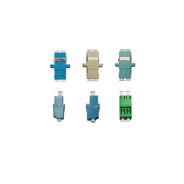
This guide provides a complete framework for understanding, identifying, and planning MPO connector gender in data center environments. Visually, male and female MPO connectors are easy to distinguish: male connectors feature two alignment pins (PIN pins), while female connectors have corresponding holes instead of pins. An MPO connection is made between a male and female connector to make sure that there is proper alignment. Interfaces on active MPO equipment, such as transceivers are usually male, so any MPO trunk cable. In modern data centers and high-density fiber optic networks, MPO (Multi-Fiber Push-On) connectors have become an essential solution for achieving fast, reliable, and scalable connectivity. You will discover the physical distinctions between male and female connectors and how to develop a gender strategy for your infrastructure, which gender connects. Whether you're supporting parallel optics like 100G SR4 or densifying an optical distribution frame (ODF), MPO is now a cornerstone of network design. This article explains: And a practical checklist to design MPO systems that scale cleanly. If you only remember one thing: MPO is a multi-fiber. In MPO and MTP fiber connector systems, Male vs Female and Pin vs No-Pin describe the same core engineering attribute: the presence or absence of alignment pins on the MT ferrule. Unlike single-fiber connectors such as LC or SC, this distinction is not optional terminology but a mandatory.
[PDF]

The core measurement procedure follows five steps: Turn on the meter and let it warm up. Most meters need a brief stabilization period before readings are reliable. Check your model's manual, but a minute or two is typical. Set the wavelength to match your light source. Fiber loss is the difference between the power when light is coupled from the transmitting end to the fiber and the power when the light reaches the receiving end. Generally speaking, when measuring the. An optical power meter measures the strength of light traveling through a fiber optic cable, giving you a reading in dBm (decibels relative to one milliwatt). The basic process is straightforward: turn the meter on, set it to the correct wavelength, clean your connectors, plug in, and read the. A power meter and light source are essential test tools that work in tandem to measure fiber optic cable loss and evaluate the quality of optical links. They provide the data necessary to quantify signal loss and pinpoint issues that could impact network performance. Here's how they work: A power. You measure optical power in dBm or insertion loss in dB. Verify light travels from transmitter to receiver. We'll give you the basic information you need and provide some printable references.
[PDF]

Average Optical Power: How bright the light is (measured in dBm). Too dim? Your signal gets lost in the fiber. Extinction Ratio: The difference between “on” (1) and “off” (0) light power. A higher ratio = cleaner signals. Transmitter Side: An electrical signal hits a laser diode (LD) or LED, which spits out light. Receiver Side: Light enters a photodetector (like a tiny solar cell), which turns it back into electricity. A built-in amplifier boosts the signal for your. The average transmitted optical power refers to the optical power output by the light source at the transmitting end of the optical module under normal working conditions, which can be understood as the intensity of light. In communication, we usually use dBm to represent optical power. However, in practical use, we adopt the average Tx power. The transmission power is related to the. This article provides an in-depth analysis of two key performance indicators of optical modules: transmitter power and receiver sensitivity. Transmitter power characterizes the average optical power output from the laser under rated conditions, while receiver sensitivity indicates the minimum. An optical module is a connecting module that serves as an optical-electrical conversion device. At the receiver end, the optical signals are reconverted into electrical.
[PDF]
00/ft, Termination $5. Total: about $40,800; per-foot average $20. Assumptions: region, specs, labor hours. Fiber-optic cable materials typically cost $1 to $6 per linear foot, depending on fiber count and cable type. Commercial building installations with 100-200 network drops generally range from $15,000 to $30,000. Single-mode fiber costs less per foot than multimode fiber, but it requires more. Buyers typically pay for fiber optic cable by length, fiber type, and installation complexity. Main cost drivers include cable grade (indoor vs outdoor, armoured), distance, and labor for trenching, splicing, and termination. This guide presents ranges in USD and practical price estimates to help. The unit cost of fiber optic cables can vary from $0. 50 per meter, depending on several variables. Here's a general pricing reference: Cable TypePrice Range (USD/meter)Simplex / Duplex Indoor Cable$0. 30Single-mode Outdoor Cable$0. 50Multimode (OM1/OM2/OM3)$0. 10 –. Single-mode fiber (OS2): This is the industry workhorse. In 2025, the base glass price has stabilized. You are looking at $0., 12-core vs 96-core) and brand. Custom-built. Whether you need singlemode, armored, or indoor plenum, this guide gives you the exact cost per foot of fiber optic cable — including installation — so you can budget without guesswork. Data aggregated from Q1 2026 contractor invoices across Texas, Ohio, and North Carolina. Cost per foot of fiber.
[PDF]

The maximum split ratio of the FBT splitter is as high as 1:32, which means that one or two inputs can be divided into outputs of up to 32 optical fibers. By dividing a single optical signal from a central Optical Line Terminal (OLT) into multiple outputs for Optical Network. In this guide, you'll learn how fiber splitters function in PON networks, the difference between PLC and FBT types, and how to choose the best model for your rollout in 2025. What Are Fiber Optic Splitters in PON? Fiber splitters are passive devices that divide one optical input signal into. FTTH relies on Passive Optical Network architecture, which enables one fiber leaving the central office to serve multiple subscribers through optical splitting. This structure eliminates the need for powered elements in the distribution segment, reducing operational costs while ensuring high. Optical splitter is an integrated waveguide optical power distribution device that serves to split optical signals. It is widely used in passive optical networks (such as EPON, GPON, BPON, FTTX, FTTH, etc. ) and plays an important role. When an optical signal is transmitted in a single-mode fiber. The FTTH network serves as the infrastructure enabling data transmission in the form of light signals over optical fiber from the operator's switching equipment directly to a home or business. Accurately understanding the principles, differences, and applicable boundaries of.
[PDF]
The Fiber Distribution Hubs are designed to store up to 576/1,152 splices and to terminate up to 192/384 fibers with SC connectors or 384/768 fibers with LC connectors. The optical cross-connection Cabinet short for OCC, or some other place call it Optical Distribution Cabinet (ODC) or Fiber Distribution Terminal (FDT), is a device designed for indoor/outdoor cable management. It is a modular solution without cable splitters and without drawing into protective tubes, with. IP65 Outdoor optical distribution cabinet 144/288/576 cores This cabinet is widely used in FTTX access network. It provides splice,storage,termination,splitting,customer cable routing functions etc.,without cables patching,which effectively solves the problems resulted by traditional distribution. Fiber optic distribution boxes, also known as fiber optic cable joint boxes or splice enclosures, are essential components of fiber optic networks. These boxes provide a safe and organized environment for splicing, distributing, and connecting fiber optic cables. SMC fiber optic distribution boxes. Optic Distribution Frame can be used in the termination and distribution of partial trunk optical cable in optical cable communication system, easy to realize connection, distribution and adjustment. ● Fully enclosed standard frame with a maximum capacity of 576 cores. ● Double-sided front door. MDP EL 288/576: 1× oval grommet for undivided cable, 4× express port II.
[PDF]

In this blog, we will explore the step-by-step process of using a beamsplitter cube effectively, along with some common applications that benefit from this powerful optical tool. Step-by-Step Guide on Using a Beamsplitter Cube. A beam splitter is an optical device that divides an incoming light beam into two separate beams. One beam is typically reflected while the other is transmitted. The ratio of reflected to transmitted light can vary based on the design of the beam splitter. Beam splitters typically come in the form of a reflective device that can split beams into exactly 50/50, half of the beam being transmitted through the splitter and half being reflected. It is a crucial part of many optical experimental and measurement systems, such as interferometers, also finding widespread application in fibre optic telecommunications. Sometimes it is referred to as a half-silvered mirror. Either way, it is a simple material that YOU could use right at home for cool DIY projects like. The beam splitter has played numerous roles in many aspects of optics. For example, in quantum information the beam splitter plays essential roles in teleportation, bell measure-ments, entanglement and in fundamental studies of the photon. Additionally, beamsplitters can be used in reverse to combine two different beams into a single one. Beamsplitters are often classified according to their construction: cube or plate.
[PDF]

An optical transceiver module, often simply called an optical module, acts as a signal conversion interface in fiber optic networks. It transforms high volumes of electrical signals into optical signals for transmission over fiber cables, or reverses the process at the receiving. In the world of fiber optic communications, optical transceiver modules play a pivotal role as interfaces that convert electrical signals to optical signals and vice versa. If you're dealing with data centers, telecommunications, or AI networking, grasping the key parameters of an optical. Optical transceivers are efficient in changing signals. These modules have many parts, each with a specific functions: Takes in electrical signals to change them. Powers lasers or LEDs to send light signals. Combines many light signals into one for. An optical transceiver, a crucial device utilized in optical communication, is an optoelectronic element, allowing the interconversion of optical and electrical signals during the information transmission. Acting as the "heart" of fiber-optic networks, these modules—ranging. This comprehensive guide breaks down the internal structure, core components (TOSA, ROSA, lasers), and operational mechanisms of SFP optical modules, enriched with technical insights and real-world applications.
[PDF]

This guide provides a clear, step-by-step explanation of how to install an SFP module correctly, based on real-world deployment practices. The fastest way to do so is by unplugging the power plug from the power outlet. This is a Class A product. In a domestic environment, this product might cause radio interference in which case the user might be required to take adequate measures Electric shock hazard. This equipment is to be. This Quick Guide covers the model: CCR2004-16G-2S+PC. You can find the product model name on the case label (ID). Or scan the QR code with your mobile phone. lv/um The most important. The Installation of the equipment must comply with local and national electrical codes. Please read the mounting instructions carefully before beginning installation. Failure to use the correct hardware or to follow the correct procedures. The CCR2004 is a high-performance multicore router with twelve 10G SFP+ ports and two 25G SFP28 ports. Before you work on any equipment, be aware of the hazards involved with electrical circuitry, and be familiar with standard practices for preventing accidents. It covers critical preparation checks, proper insertion techniques, hot-swap and safety considerations, common installation mistakes, and practical. The Cisco 8000 series routers support both ZR and ZR+ modules. The Cisco 8200 Series uses a single Cisco Silicon One ASIC to deliver full routing functionality. These fixed port, high-density routers provide 10.
[PDF]

This article helps network engineers, field techs, and IT managers choose the right single-mode transceiver campus optics by tying IEEE Ethernet requirements to day-to-day deployment constraints: reach, budgets, DOM behavior, and operational limits. Huawei eKit offers a comprehensive series of pluggable optical modules in the Huawei eKit portfolio. The wide variety of modules gives you flexible and plug-and-play options for all types of interfaces. You will also get a practical checklist, common. Multimode and Singlemode optical modules differ in terms of fiber type, transmission distance, cost, and application scenarios. Understanding these differences is the first step in selecting the right module. This saves space and money. Dual fiber modules use two fibers. They are easier to set up and give steady communication. Its primary function entails converting electrical signals into optical signals. This assembly comprises a light source, such as a laser diode or a semiconductor light-emitting diode (LED), an optical interface, a. A single-mode receiver is an optical device that converts incoming light signals—carried over single-mode fiber (SMF)—back into electrical data. Unlike multimode receivers, which accept wider light beams from LEDs or VCSELs, single-mode receivers pair exclusively with laser-based transmitters.
[PDF]

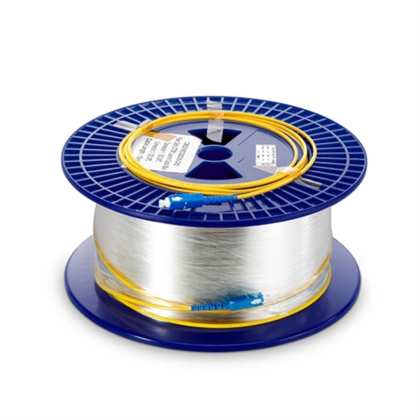
Fiber optic cables often follow a color-coding system to indicate their type: Single-mode fibers - Typically yellow. Multi-mode fibers (OM1 & OM2) - Usually orange or sometimes gray. Choosing the right type of fiber optic cable is essential for reliable and cost-effective network performance. The two main types — Single Mode (SM) and Multimode (MM) — differ in construction, performance, and application. This guide explains how to identify them by appearance, labeling, and. When figuring out if a fiber cable is single mode, one must know the different classifications. Essentially, fiber optics are mainly categorized as: Single Mode Fiber (SMF): This type features a small core and uses laser technology to send a single light mode. Single mode fibers are used for. Knowing how to tell the difference between single mode and multimode fiber is crucial for network efficiency; the core distinction lies in the fiber's core diameter and how light travels through it, affecting bandwidth, distance, and cost. This allows for a single mode of light to travel through the core. With clear tables and updated details, it serves as a comprehensive reference for technicians handling modern fiber optic installations. We'll cover single mode, multimode, and armored fiber cables below. This small diameter core, typically around 9 microns in diameter, allows only one.
[PDF]