
NOTE: Insert the end of a colored wire into one of the holes in a butt connector. With the wires pushed tightly against the far inside wall of the connector, squeeze the red button until it depresses. The OS-8171 Beam Splitter is designed to be used with the OS-8170 Brewster's Angle Accessory and the OS-8539 Educational Spectrophotometer System. ) In the Brewster's Angle experiment, the Beam Splitter is used with a. am Splitters/Combiners. This document describes this product line, as well as general operation guidel into two output beams t beams of equal power. The standard product is designed for use in the visible spectrum 400-700 nm wavelength). Custom Surgical Beam Splitter sends 50% of the light to the eyepieces and 50% to the smartphone camera. If you want to understand more about how beam splitter works, watch the video below. It is not necessary to. As title. in your towing vehicle manual. Be sure the hitch is installed onto the vehicle. Releasing the pin before will cause supp owards the engine faster than you can let go. This is because if a fire. Meadowlark Optics presents its VersalightTM wire grid polarizing beam splitters. Manufactured for wavelength ranges between 420 and 2600 nm, this polarizer is ideal for broadband and wide field-of-view applications. Wire grid polarizing beam splitters are manufactured out of our Versalight wire.
[PDF]
Identify the Pins: Ensure you correctly identify the live (L) and neutral (N) pins. Connect to Power Source: Insert the 2 pin plug into a compatible power outlet. The 2 pin connector is one of the most versatile and simple connectors. It can be used for a variety of different applications. These small, yet powerful components are found in nearly every device--from smartphones to industrial machinery--connecting electrical circuits and ensuring the smooth. A 2-pin DC power connector offers a compact and efficient solution. In this guide, you'll learn exactly what these connectors are, where they're used, and how to choose the best one for your application. It is commonly found in household appliances and electronics. Neutral Pin – Completes the circuit by returning the current. Since there is no earth pin, these plugs are suitable only for devices with double. The cold-pressed wiring of electrical heavy-duty connectors mainly includes the following steps: 1. Prepare tools and materials: You need to prepare cold-pressed terminals, wire strippers, wire crimping pliers, screwdrivers and other tools and materials. I go over all the components and steps to put together a 2 pin Deutsch connection.
[PDF]

In this beginner-friendly guide, we'll explain what it is, why the “APC” matters, the different types you can buy, how to select the right model, and how to install and test it correctly. What is an SC/APC Fiber Optic Adapter?. Fiber optic adapters, also known as couplers, play a crucial role in fiber optic networks by providing a connection point between two fiber optic connectors. They enable seamless and reliable optical signal transmission between different fiber optic cables, connectors, or devices. Using the wrong type or neglecting cleaning can lead to signal loss and unstable connections. This guide covers adapter types, selection criteria, cleaning tips, FAQs, and B2B customization options to help businesses build reliable and scalable fiber networks. It ensures precise alignment between fibers and facilitates effective transmission of optical signals. Without the proper adapter, signals can degrade or become unstable, which can dramatically decrease the reliability of a network.
[PDF]

In this step-by-step guide, we will walk you through the process, ensuring that you can seamlessly connect your optical cable and enjoy a clear and uninterrupted audiovisual experience. Optical cables are becoming increasingly popular for transmitting high-quality. Optical audio cables can easily improve your TV's sound by connecting to external speakers. Learning how to connect an optical cable is easy, but there are a couple of gotchas that you should know. Here are the basics: Identify the optical output; if there's a protective plastic cap, remove it. The most common types are: The Toslink optical cable is a standard for transmitting digital audio signals. It uses a plastic or glass fiber to carry light signals from one. You can connect an older flat screen TV to ANY Stereo system, Surround Sound system, or Soundbar. This video shows you step by step how to make audio connections using an digital optical cable. You can use an optical connection even if your audio system does not have an optical socket, and by using. One of the easiest ways to achieve high-quality sound is to connect your TV to a home theater system or soundbar. Easily connect your optical audio cable to your TV! Follow our step-by-step guide for a hassle-free setup and enjoy crystal-clear sound. No wonder how to improve TV sound, right? When the sound is weak, for example, when using an analog sound source, then an optical audio cable possibly will be the.
[PDF]

Learn how to properly install a pigtail connector in just a few easy steps. No description has been added to this video. Enjoy the videos and music you love, upload original content, and share it all with friends, family, and the world on YouTube. Pigtail connections are most frequently used to ground a switch or electrical outlet and for electrical devices that need to connect to multiple circuit wires. They also come in handy to lengthen circuit wires that are too short to reach a device. A pigtail is composed of three strands of wire. A pigtail connector is a short length of insulated electrical wire that is pre-attached to a device, terminal, or fixture, serving as a flexible bridge between the fixed wiring system and the component. Whether you are a DIY enthusiast or someone facing an electrical issue, understanding how to replace a pigtail connector can be invaluable. This article will walk you through the necessary steps and provide. This is where quality automotive connector replacement steps in. Often, rather than pay thousands of dollars for an entire harness, you can simply replace the damaged connector by a careful de-pin/re-pin or an accurate wire repair. Want more automotive electrical wire repair videos? Click Here Hear. The National Electrical Code (NEC) requires a pigtail to be at least six inches long. Although this standard applies to house wiring, we can use the same for vehicle wiring.
[PDF]

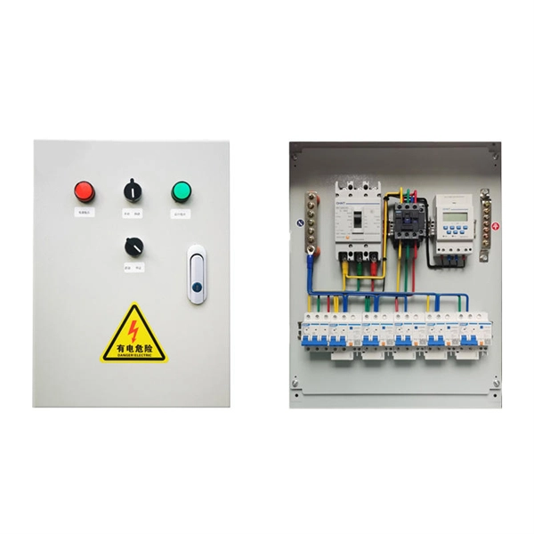
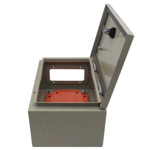
This video shows real on-site footage of electrical installation, demonstrating safe and standardized wiring methods used by professionals. more Learn how to wire a distribution box step by step! This video shows real on-site footage of. Understanding the wiring diagram of an electrical panel box is essential for electricians and homeowners alike, as it allows them to troubleshoot any electrical issues, carry out repairs, or make additions to the system. The electrical panel box wiring diagram provides a visual representation of. A distribution box, also known as an electrical distribution board, is a critical component in electrical systems. It serves as a central point for distributing electricity to various circuits in a building or facility. This section will explain its function, types, and the importance of correct. Understanding how to safely set up the main connections of a home's power distribution system is essential for ensuring reliable and secure operation. A correct installation process minimizes the risk of electrical faults and increases the longevity of your setup. Proper knowledge is crucial for. Material preparation: Prepare the required circuit breakers, wires, wiring ties and other materials, and ensure that they meet the design drawings and installation requirements. Whether you're an electrician or a DIY enthusiast, this guide will help you understand the basics of home electrical distribution. What is Distribution Board? Distribution board.
[PDF]

In this article, we'll provide step-by-step instructions on how to install a round junction box in a wall, as well as tips on safety and proper wiring techniques. First, you need to determine the. A junction box provides a code-approved place to house wire connections, whether for outlets, switches, or splices. Here's how to install one. We may be compensated if you purchase through links on our website. It acts as a central connection point for various electrical wires, allowing for the easy distribution of electricity to different fixtures and devices. A properly installed and wired junction box ensures the safety and. Nothing is more dangerous and aggravating than loose wires in a junction box. In this video you'll learn how to wire junction boxes correctly. You'll also see our favorite tools to complete this task. Thanks for watching and Have A Great Day. more. Learn how to install a junction box safely, from choosing the right box and mounting it correctly to making secure splices and following basic code-safe practices. This metal or plastic housing contains wire connections, protecting them from environmental factors and physical damage. Junction boxes are fundamental in residential and.
[PDF]

In this tutorial, I will show you how you can connect the Optocoupler to Arduino, read the data as Analog or Digital, and if necessary convert the analog values to digital, and how to reduce noise from the sensor. The Infrared Slotted Optical Optocoupler Module is a device that uses infrared light to transmit signals between two electrically isolated circuits. It consists of an infrared emitter (LED) and a photodetector (phototransistor) housed in a slotted enclosure. When an object passes through the slot. Slotted Optocouplers (Photo Interrupters) are very useful sensors, often included in Arduino projects to detect position of moving objects, measure speed of rotation, or linear motion, frequency of events, and many others. They are easy to use, but it is important to understand how they work, so. This tutorial is a comprehensive, practical guide to the Speed Sensor / Tacho Sensor (Slot-Type Optocoupler) (Leobot Product #245). Moreover, a simple application is programmed that shows how to wire and how to program an Arduino when working with the module. In this tutorial, the module is used as an “digital input board”. If you want to use the. In this project, I will talk about Phototransistor Optical Interrupter Switches (Opto Coupler) Module, how this module works and helps in determining the speed of a rotating object and finally I will show you how to Interface Optical Interrupter Switch Sensor with Arduino and measure the speed of a.
[PDF]

The maximum distance of copper is around 328 feet (100 meters), which is a far shorter range than is offered by either of the fiber optic cable types. This is because fiber optic cable is not affected by attenuation, dispersion, or EMI in the same way that copper is. Many factors decide the fiber cable distance, but the key factors include the below six aspects. Attenuation First is the attenuation of the optical fiber. For some. Fiber optic cable transmission distance is determined by two primary physical factors that affect signal quality as light travels through the fiber medium. The selection of fiber optic cables over copper wires or vice versa depends on factors such as bandwidth, distance, and cost of transmission. Fiber optic cables transmit data using light waves, enabling higher. Fiber optic cables have revolutionized modern communication networks by enabling blazing-fast data transmission across vast distances. However, fiber cable runs are not limitless. However, fiber optic cable performance. Q: Is there and electromagnetic interference with optic cables? A: The fiber is glass and the cable is plastic, neither of which are affected by electromagnetic interference. There is a cable used in electrical transmission lines called OPGW- optical power ground wire - that has fiber inside a wire.
[PDF]

This guide breaks down their technical differences, performance metrics, real-world applications, and how to choose the right one for your network—all optimized for Google SEO and packed with actionable insights. Introduction: Why Fiber Optic Cable Type Matters. Single mode fiber optic cable is made up of a small diameter glass or plastic core surrounded by cladding, which is a layer of reflective material. This small diameter core, typically around 9 microns in diameter, allows only one mode of light to pass through, resulting in a narrower beam of light. But not all fiber cables are created equal: multimode (MM) and single mode (SM) fibers are the two primary types, each engineered for specific use cases, from short-range data center connections to transcontinental telecom backbones. Whether you are an IT specialist, a network manager, or just a curious individual interested in the. As explained by the Fiber Optics Association, fiber optics is the communications medium that sends optical signals down hair-thin strands of extremely pure glass cores. The core is surrounded by the cladding that traps the light in the core. Fiber types are identified by the diameters of the core. The article compares single-mode and multimode fiber optic cables, especially in how their core design, light propagation, and use-cases differ. Core Diameter Single mode fiber: one that has a small light-carrying core that is about 9 micrometers (µm) in diameter.
[PDF]

Use your pliers to twist the pigtail wire and the ground wire together. Snip the sharp edge at the terminal and then insert it into the wire cap. If your metal box is in use, secure a green screw in the threaded opening at the back of the metal box. In this guide, I will teach you how to pigtail ground connections in metal and electrical boxes, and how to make a perfect pigtail. Below I will provide straightforward. Pigtailing is an essential electrical wiring technique used when adding devices or when there aren't enough spaces in a junction box. 📌 What You'll Learn in. If you have a pigtail for three wires (say # 14 AWG if that makes a difference) together in a wire nut but you want to add another wire to the mix. Is the proper method to undo the wire nut and untwist them and try to straighten out all three as best as possible? (In IT there was a tool to. Before diving into the mechanics of twisting, it's crucial to understand the two primary components involved: the wire itself and the pliers you'll be using. The success and durability of your twist depend heavily on selecting the appropriate materials and tools for the job. This technique is often employed when three or more wires need to be joined, ensuring that the. A pigtail wire is a short cable used to lengthen short wires. Also, it can join several wires to become a single conductor for electrical connections. The National Electrical.
[PDF]
Remove the connector by carefully pulling it straight out of the port when the latch has been released. This guide outlines proper methods to safely remove fiber optic cable from modems in your home or office. As an experienced technology writer who has covered broadband advancements for over a decade, I aim to provide readers with trustworthy instructions endorsed by industry experts. Having. Fiber optic connectors are essential components in fiber optic networks, providing a reliable connection between cables and equipment. Removing these connectors requires care to avoid damaging the delicate fibers or the connector itself. Fiber optic cables are different from traditional copper cables, as they use light to transmit data, and the connectors are more sensitive. This is a popular video tutorial that is often requested by viewers. Release the latch: The SC connector is secured in place by a latch on the side. Step 1: Prepare the necessary tools and materials, including the fiber optic connector, cable stripper, fiber cleaver, and lint-free wipes. Ensure that everything is clean.
[PDF]

In this complete wiring diagram guide, we will walk you through the step-by-step process of wiring a mag starter. We will explain the purpose and function of each component, provide clear diagrams, and offer expert tips to ensure a successful installation. Whether you're a beginner or an. For proper integration of an electromagnetic securing device, ensure the power supply matches the specified voltage–typically 12V or 24V DC. Incorrect voltage can cause malfunction or reduced holding force. Use a regulated power source to prevent current fluctuations that might trigger false alarms. Understanding the wiring diagram of a magnetic starter is essential for technicians and electricians who work with electric motors. This diagram provides a visual representation of the components and connections involved in the operation of the starter. Once you have everything ready, you can proceed with the installation process. Begin by determining the appropriate position for the magnetic lock on the door. Quick guide on how to wire an access control system with power supply, lock, and exit button. more Quick guide on how to wire an access control. Installing a magnetic door lock can be a cost-effective and reliable way to secure your doors. These locks use an electromagnetic current to keep the door securely closed, and they are commonly used in commercial and residential buildings.
[PDF]

Arduino-Powered Data Transmission with Fiber Optics Welcome to our video tutorial on optical communication with Arduino, designed to be easy t. more. They consist of a transmitter on one end of a fiber and a receiver on the other end. Most systems use a "transceiver" which includes both transmission and. I'm going to use HFBR 1414 fiber optic transmitter module which is manufactured by Broadcom. It is a low-cost high-power transmitter that is designed for use in industrial power generation, power distribution, medical transportation and gaming applications. Internally, the optical fiber consists of a highly reflective central core, which acts like a light guide. Media converters are special fiber optic transceivers used to convert from one type of cable (the media) to another, typically from copper cables to fiber optics, although some media converters will convert from one fiber type to another, e. multimode to singlemode. The FOA Guide has a page about. A fiber optic transceiver (also called an optical transceiver) is a compact module that both transmits and receives data signals through optical fibers. It serves a dual purpose — transmitting electrical signals as light pulses and receiving light pulses to convert them back into electrical form.
[PDF]

This handbook covers the code of practice in protection circuitry including standard lead and device numbers, mode of connections at terminal strips, colour codes in multicore cables, dos and donts in execution. Also principles of various protective relays and schemes including special protection. Relay systems protect high-voltage equipment and transmission lines to ensure safe, stable systems. Ensuring that. lectrical work practices. See NFPA 70E in the USA, e conduit nut provi ource termination point. * NOTE: When connecting the control side of this device (#18 wires) to power line circuits, provide curre. 1/3HP@120V. The testing and verification of relay protection devices can be divided into four groups: Type tests are needed to prove that a protection relay meets the claimed specification and follows all relevant standards. Since the basic function of a protection relay is to correctly function under abnormal. Manual intended for personnel responsible for installing, commissioning and using VIP protection 400. The handbook for protection engineers includes guidelines on protective circuitry, protective relay principles, and testing procedures for switchgear and relays. It covers standard codes, wiring practices, and norms for protecting generators, transformers, and lines, and provides detailed.
[PDF]