
Arduino-Powered Data Transmission with Fiber Optics Welcome to our video tutorial on optical communication with Arduino, designed to be easy t. more. They consist of a transmitter on one end of a fiber and a receiver on the other end. Most systems use a "transceiver" which includes both transmission and. I'm going to use HFBR 1414 fiber optic transmitter module which is manufactured by Broadcom. It is a low-cost high-power transmitter that is designed for use in industrial power generation, power distribution, medical transportation and gaming applications. Internally, the optical fiber consists of a highly reflective central core, which acts like a light guide. Media converters are special fiber optic transceivers used to convert from one type of cable (the media) to another, typically from copper cables to fiber optics, although some media converters will convert from one fiber type to another, e. multimode to singlemode. The FOA Guide has a page about. A fiber optic transceiver (also called an optical transceiver) is a compact module that both transmits and receives data signals through optical fibers. It serves a dual purpose — transmitting electrical signals as light pulses and receiving light pulses to convert them back into electrical form.
[PDF]

This helps keep fiber optic cables safe from harm and signal problems when you put them in. Use the right lubricant. Follow the rules for tension and bend radius. Try new methods like air blowing. Use smart. Fiber optic cable is surprisingly strong, durable and pliable; however, several best practices should be followed to ensure a successful cable installation. This article explores recommendations for pulling and installing fiber optic cable. This makes sure the cable pull is smooth and safe. Use smart monitoring devices. The Future Ready Solutions Tools & Test. A duct is available from point A to point B, a pull tape is blown in, a fiber optic cable is attached to it and the cable is pulled through the duct. Sounds simple, doesn't it. Recent observations and conversations with more than a few people in the fiber optic business have indicated. Route plan to ensure the duct run maintains the minimum bend diameter of the cable. For more information and all recommendations for installation, refer to Corning Optical Communications Standard Recommended Procedure SRP 005-011, "Duct Installation of Fiber Optic Cable". more Route plan to ensure.
[PDF]
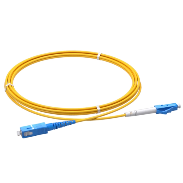
In order to achieve consistent and compatible fibre systems, it is recommended that the convention defined in ISO / IEC 11801 is used where channel A (right) is the input and channel B (left) is the output. Fiber optics relies on a bidirectional transmission where the transmitter port on one end connects to the receiver port on the other end. Since fiber optic links require a two-way - or duplex - connection, there is potential for errors in installation by connecting transmitter to transmitter or. Fiber polarity is the direction that light signals travel from one end of a fiber optic cable (link) to the other. Although it may seem obvious, fiber optic polarity is a frequent source of confusion and. Polarity in fiber optic networks refers to the alignment of transmit (Tx) and receive (Rx) signals between interconnected devices. This principle becomes more complex when dealing with multi-fiber MPO (Multi-Fiber Push-On) connectors, which typically house 12, 24, or even 48 fibers in a single. Because fiber systems are directional, maintaining polarity is crucial. It defines the direction that optical signals travel inside the fiber. Without polarity, data won't flow the way it needs to. Ensuring proper polarity means that “transmit” talks to “receive.
[PDF]

Not all splitters are created equal. Here are the main types you'll encounter: The "1×N" notation indicates one input fiber and N output fibers. A 1×2 splitter divides the signal into two outputs, while a 1×8 splitter divides it into eight. The more splits, the. By dividing a single optical signal from a central Optical Line Terminal (OLT) into multiple outputs for Optical Network Terminals (ONTs) at users' homes, splitters eliminate the need for dedicated fibers to each residence—slashing infrastructure costs while scaling network reach. This guide. A fiber-optic splitter, also known as a beam splitter, is based on a quartz substrate of an integrated waveguide optical power distribution device, similar to a coaxial cable transmission system. The optical network system uses an optical signal coupled to the branch distribution. The fiber optic. Optical couplers can split or join signals in fibers. You can connect many users to one port with 1:n or 2:n splitters. These devices work both ways, which helps strong network communication. In a Passive Optical Network (PON), a single optical fiber carries massive amounts of data using light. They are named by the number of inputs and outputs, so a splitter with one input and 2 outputs is a 1X2, and a PON splitter with one input and 32 outputs is a 1X32.
[PDF]
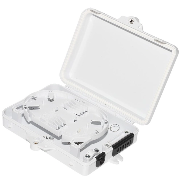
Capable of serving up to 4/8 subscribers, it functions as an essential termination point in FTTx communication networks, accommodating fiber splicing, splitting, and distribution effectively. Elevate your telecommunications infrastructure with the COMX Fiber Distribution Box (FDB), expertly designed for seamless fiber management and distribution. This robust FDB integrates a connectorized splitter, optimizing fiber connectivity and facilitating swift deployment in both indoor and. The FDB-12C Fiber Optic Distribution Box is an outdoor enclosure designed for splicing, splitting, and drop cable connectivity to meet the demands of high-density fiber-to-the-home (FTTH) and fiber-to-the-curb (FTTC) access networks. With capacity for 12 customer connections in a compact IP55 wall. Indoor FTTH Fiber Distribution Box, optical fiber distribution box is used for the fusion splicing, splitting, wiring transmission, and other functions of the optical transmission terminal. It can effectively terminate, protect and manage the optical cable. It is necessary equipment in network. Fiber optic cross connect cabinet, also known as fiber distribution hub (FDH). It play a crucial role in determining the network coverage capacity of a fiber optic network. It provides a structured environment for routing cables, managing splices, and accommodating termination modules. FDBs are used to organize incoming and outgoing cables.
[PDF]
The cost to install fiber optic cable ranges from $1. 50 to $42 per foot, with installation costs accounting for 60-80% of total project expenses. According to the Fiber Broadband Association's 2025 report, median costs are $8 per foot for aerial builds and $18 per foot for. Homeowners and businesses typically pay for fiber optic cable installation based on distance, conduit needs, and labor. The main cost drivers include material type, run length, trenching or aerial work, and any required permits or inspections. This article outlines cost expectations. The initial cost of installing fiber optic cables can vary depending on the chosen installation method and specific project requirements. fiber projects, we've assembled current material rates, labor burdens, and hidden fees. Whether you need singlemode, armored, or indoor plenum, this guide gives you the exact cost per foot of fiber optic cable —. Fiber optic cable installation costs between $1,500 and $7,000 for your home, with prices varying by cable length and installation method. The installation type you choose and the layout of your property determine the total labor and materials needed for your project.
[PDF]

Fiber optic network design (896. 83 KB). I'm needing symbols for common fiber optic components, cables, connectors, backbone ports, etc. Can anyone help me out? Some examples of a diagram would also help. 10-27-2018 01:41 AM Do you know if there's some symbol standard fir this kind of schematics? I surely don't know. If you can be helpful. Free CAD and BIM blocks library - content for AutoCAD, AutoCAD LT, Revit, Inventor, Fusion 360 and other 2D and 3D CAD applications by Autodesk. CAD blocks and files can be downloaded in the formats DWG, RFA, IPT, F3D. You can exchange useful blocks and symbols with other CAD and BIM users. See. Search by part number or description such as CAT5, CAT6, OSP, etc. Sort by any of the table headers. Use the drop down menu to filter by product category and type. Sort by any. Welcome to the Corning LANscape® Solutions Product Drawings Resource Center, your complete source for our optical hardware component drawings. The two-dimensional and isometric hardware products drawings are available in PDF (Adobe® Acrobat®), DXF (AutoCAD®), VSS (Visio® Stencil) formats, and. Be among the first to receive important product updates, insights and news. Of all these options, the most favored one is optical cables because they offer uninterrupted swift data transmission.
[PDF]
A distribution box serves as a central point for managing and distributing fiber optic cables. This device ensures reliable and efficient connectivity between various network components. The importance of a distribution box cannot be. Fiber distribution box is made of high-strength engineering plastics, anti-UV, anti-aging ability. This article provides a comprehensive overview of fiber optic distribution boxes, essential components in modern telecommunications networks that enhance data transmission efficiency and reliability. Why do operators, designers, and installers use additional fiber optic hardware racks for cable and fiber management? The active electronics are the most expensive part of the. Enter the Optical Distribution Frame (ODF)—a foundational component that serves as the “nerve center” for fiber optic management, enabling seamless connectivity, efficient maintenance, and scalable growth. This guide demystifies ODF, exploring their design, core functions, types, and how they. Embodying Clearfield's commitment to modularity and flexibility, our FieldSmart Active Cabinets are rigorously tested and certified to safeguard critical infrastructure in even the most challenging environments. Designed with innovative options for fiber and active equipment craft separation, these.
[PDF]

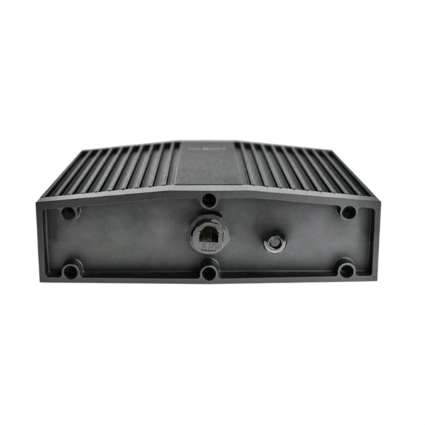
This comprehensive guide breaks down the internal structure, core components (TOSA, ROSA, lasers), and operational mechanisms of SFP optical modules, enriched with technical insights and real-world applications. Optical Modules (also known as Optical Transceivers) are critical components in fiber optic communication systems. As the core optoelectronic devices operating at the Physical Layer of the OSI model, their primary function is to perform electro-optical and photo-electric conversion during signal. In the era of 5G, AI, and high-speed data centers, optical modules serve as the core bridge for converting electrical signals to optical signals (and vice versa), enabling fast, reliable data transmission across networks. They are used in fiber optic communication systems to transmit data over long distances with minimal loss and interference. This article systematically identifies common anomalies during optical module installation. Combining hardware principles with practical experience, it. When the industry speaks of optical modules, it refers specifically to small, hot-swappable packaged optical modules, which are used on equipment ports and can be hot-swapped during operation, and are mainly used to convert the electrical signals in equipment (usually switches or router equipment).
[PDF]

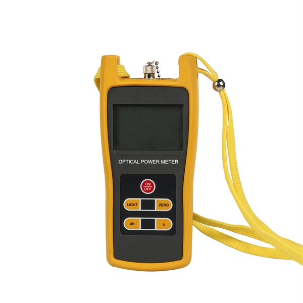
To use a power meter for fiber optic testing, always clean connectors first with lint-free wipes or click-to-clean tools. Select the correct wavelength and set your reference. You measure optical power in dBm or insertion loss in dB. Consistent procedures ensure accuracy. Verify light travels from. The most basic fiber optic measurement is optical power from the end of a fiber. This measurement is the basis for loss measurements as well as the power from a source or presented at a receiver. Typically both transmitters and receivers have receptacles for fiber optic connectors, so measuring the. An optical power meter measures the strength of light traveling through a fiber optic cable, giving you a reading in dBm (decibels relative to one milliwatt). This article will guide you through the methods, instruments, and key considerations for measuring fiber. Fiber optic cabling is the high-performance core of today's datacom networks. As network speeds and bandwidth demands increase, fiber performance requirements have become more stringent. Fiber testing is more important than ever. An OPM uses a photodiode to generate an electrical current proportional to optical power.
[PDF]

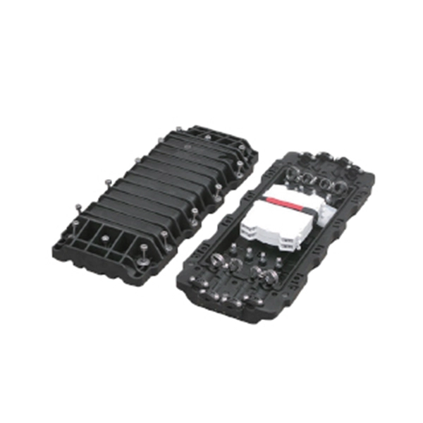
Fiber Optic Welding How To Joint Fiber Optic Cablesplicing fiber optic cable,fiber optic splice,fiber optic,fiber optics,fiber splice,how to splice,fibre opt. The optical fiber connection adopts the fusion splicing method. The whole process is similar to the welding of metal wires, and it is generally carried out by electric isolation. At the moment, there are two methods of connection: Thermal welding of optical fibers consists in bringing the ends of the conductor to melting using a fiber optic splicer, and more specifically - located inside the electrodes. The welded ends are then pressed and a weld is formed. The most work is waiting for installers, whose tasks can be divided into several stages: In this part, we will deal with the second stage, i. welding, which is considered to be one of the most difficult parts of installers' work in. Open the stripping tube and wipe the grease on the optical fiber with toilet paper and alcohol cotton. On the welding disc, make the optical fiber precoil first and cut the optical fiber into an appropriate length to facilitate the coil fiber work after welding. Add heat shrink tube. Procedure. Another method is to use the so-called mechanical welding. It uses special parts that are prepared in advance to connect the two ends. Thanks to this, you can connect two ends of the cable with a ready-made splice, without the need to use an optical fiber splicer. While this method may appear to be.
[PDF]

Learn how to install a fiber optic termination box step-by-step for FTTH projects. Covers mounting, splicing, routing, labeling, and testing for indoor/outdoor use. Installing a fiber optic termination box is one of those jobs that looks simple on paper, but it's easy to do poorly in the field. A. A fiber termination box is the standard instrument used in fiber optic networks to connect, secure, and protect optical fibers at the terminating point. It functions as a junction between the incoming fiber cable and the outgoing customer-side fiber cable, where one fiber can be spliced, patched. FTTP or fiber To The Premises applications have reinforced the importance of reliable and stable fiber optic terminations. They also feature resistance to moisture, impact, chemical exposure. A common question we receive is: How do you use a fiber-optic termination box? We recommend using a termination box if you're ordering an assembly with more than two strands. It helps keep your connectors free from contamination and dust, while also keeping your assembly neat and organized. It serves as a termination point for optical fibers, providing a secure and organized space for connecting and managing fiber optic cables. The following steps provide a detailed installation guide for fiber termination boxes: Before starting the installation, you will need the.
[PDF]

Here's a step-by-step guide to help you set up your fiber distribution box seamlessly: Before installing the fiber distribution box, ensure that your optical cables are properly prepared for connection. The optical fiber distribution box allows people to easily access the optical fibers in the box, and can well protect the optical fibers. In addition, the drawer structure also facilitates high-density wiring and good cable management. However, because optical fibers are fragile and can be easily. Keeping this page as a placeholder for now. Have any questions? Talk with us directly using LiveChat. Fix the rack to the ground with expansion bolts. Top installation: Dimensions of four connection holes on the top according to the. This instruction describes the installation of the Fiber Distribution Frame (FDF) manufactured by Corning Optical Communications. To order accessories that are purchased separately, contact Corning Optical Communications customer care for assistance. Read and understand this procedure (as well as. Optical fiber distribution frame is the wiring connection equipment between optical cable and optical communication equipment or between optical communication equipment. Distribution boxes are especially essential for FTTH networks, where they enable the efficient connection and management of optical fibers from a central.
[PDF]

How to Use Optical Power Meter TR-504 | Optical Power Meter Working| Testing OPM, VFL, RJ45 | TRICOM In this video, we walk you through how to use the TRICOM TR-504 Optical Power Meter and explain how it works. Learn how to test fiber optic cables, OPM, VFL . Optical power meters are a key element in the optimization and maintenance of such optical networks and of their components. In this article, learn: What is an optical power meter? An optical power meter (OPM) measures the power levels of light signals in devices that transmit data or power using. An optical power meter measures the strength of light traveling through a fiber optic cable, giving you a reading in dBm (decibels relative to one milliwatt). The basic process is straightforward: turn the meter on, set it to the correct wavelength, clean your connectors, plug in, and read the. OPM interface: insert the fiber to be tested, test the optical power. An optical power meter is a tool that measures the number of optical power in a cable is fiber-optic. It helps engineers verify the performance of optical fiber systems, ensuring that the signal strength meets requirements, and is an essential tool for communication network maintenance and troubleshooting.
[PDF]
This visualization shows the growth of the undersea cable network, global internet peering capacity, and the distribution of IP addresses via BGP announcements over time. Use the controls at the top to play the animation or step through year by year. The Submarine Cable Map is a free and regularly updated resource from TeleGeography. TeleGeography's comprehensive and regularly updated interactive map of the world's major submarine cable systems and landing stations. For more details and insights, please read this. Dongguan TW-SCIE Co.,Ltd is a professional manufacturer of FTTH drop cable, indoor/ outdoor fiber optic cable and patch cord. Products are conform to ISO 9001 standard. Welcome to visit us: Krasnopresnenskaya Naberezhnaya, 14. Dongguan Guanhong Optical Cable Co., Ltd (referred as Fiberplan) is a high-tech enterprise integrating the research, manufacture and marketing. And we can produce customized products as customer's require. The facility commenced operations in 2003, and its purpose was publicly revealed by AT&T technician Mark Klein in 2006. Room 641A is located in the SBC Communications building at 611 Folsom Street, San Francisco, three floors of which were occupied by AT&T before SBC purchased AT&T.
[PDF]