
In this case use an optical power meter (OPM) and test the input port of the splitter for the optical power level (dBm) from the OLT at 1490 nm. If there is no or reduced power then the patchcord or OLT is the culprit. If the power level is reduced it could be as simple as a. So for this simple 1X2 splitter, how do we test it? Simply follow the same directions for a double-ended loss test. Attach a launch reference cable to the test source of the proper wavelength (some splitters are wavelength dependent), calibrate the output of the launch cable with the meter to set. Optical splitters in the outside plant (OSP) are used mostly in passive optical networks (PONs) for fiber-to-the-user (FTTx) networks, and are often overlooked as failure points. In this article I focus on a few basics of optical splitters, their applications, typical causes of failures, and how to. Now, we test the simplest 1x2 optical splitter as the picture shown below. 001 dB), OTDR (for reflection event detection). Cleaning tools. The CertiFiber® Pro Optical Loss Test Set (OLTS) can be used to check that the loss of a PON Splitter (often referred to in various standards as a non-wavelength-selective or wavelength-selective branching device) to check that it is within the allowed defined limits. The CertiFiber® Pro has an.
[PDF]

Arduino-Powered Data Transmission with Fiber Optics Welcome to our video tutorial on optical communication with Arduino, designed to be easy t. more. They consist of a transmitter on one end of a fiber and a receiver on the other end. Most systems use a "transceiver" which includes both transmission and. I'm going to use HFBR 1414 fiber optic transmitter module which is manufactured by Broadcom. It is a low-cost high-power transmitter that is designed for use in industrial power generation, power distribution, medical transportation and gaming applications. Internally, the optical fiber consists of a highly reflective central core, which acts like a light guide. Media converters are special fiber optic transceivers used to convert from one type of cable (the media) to another, typically from copper cables to fiber optics, although some media converters will convert from one fiber type to another, e. multimode to singlemode. The FOA Guide has a page about. A fiber optic transceiver (also called an optical transceiver) is a compact module that both transmits and receives data signals through optical fibers. It serves a dual purpose — transmitting electrical signals as light pulses and receiving light pulses to convert them back into electrical form.
[PDF]

Product Range: PLC splitters, FBT splitters, fiber optic adapters, patch cords Price Range: $5 to $150 depending on splitter ratio and specs Overview: TTI Fiber is a global supplier known for quality optical components. FBT (Fused Biconical Taper) Fiber Optic Splitters. These devices splits the fiber optic signal from a single Input to two Outputs. Available in 50/50, 30/70, and 90/10 spit ratios. A fiber optic splitter is different from WDM. WDM can divide the. FBT (Fused Biconic Taper) Coupler Splitter is a commonly used fiber optic coupler and splitter for distributing optical signals to multiple output channels. FBT splitters are reliable and cost-effective, typically used for smaller split ratios like 1x2 or 1x4. The physical packaging or form factor of a splitter is crucial. FBT Coupler Splitters is widely accepted and used in passive optical networks, especially for instances where the split configuration is smaller (1×2, 1×4, etc. FBT is the traditional technology in which two fibers are placed closely together, typically twisted around each other and fused. FBT Fiber Splitter, also known as a fiber optical coupler, separates fiber optic light into many portions using a predetermined ratio. Unlike PLC splitters, FBT splitters employ distinct splitting methods and may be constructed using singlemode, multimode 62. 5, or multimode 50 fibers.
[PDF]

How to Use Optical Power Meter TR-504 | Optical Power Meter Working| Testing OPM, VFL, RJ45 | TRICOM In this video, we walk you through how to use the TRICOM TR-504 Optical Power Meter and explain how it works. Learn how to test fiber optic cables, OPM, VFL . Optical power meters are a key element in the optimization and maintenance of such optical networks and of their components. In this article, learn: What is an optical power meter? An optical power meter (OPM) measures the power levels of light signals in devices that transmit data or power using. An optical power meter measures the strength of light traveling through a fiber optic cable, giving you a reading in dBm (decibels relative to one milliwatt). The basic process is straightforward: turn the meter on, set it to the correct wavelength, clean your connectors, plug in, and read the. OPM interface: insert the fiber to be tested, test the optical power. An optical power meter is a tool that measures the number of optical power in a cable is fiber-optic. It helps engineers verify the performance of optical fiber systems, ensuring that the signal strength meets requirements, and is an essential tool for communication network maintenance and troubleshooting.
[PDF]

In this blog, we will explore the step-by-step process of using a beamsplitter cube effectively, along with some common applications that benefit from this powerful optical tool. Step-by-Step Guide on Using a Beamsplitter Cube. A beam splitter is an optical device that divides an incoming light beam into two separate beams. One beam is typically reflected while the other is transmitted. The ratio of reflected to transmitted light can vary based on the design of the beam splitter. Beam splitters typically come in the form of a reflective device that can split beams into exactly 50/50, half of the beam being transmitted through the splitter and half being reflected. It is a crucial part of many optical experimental and measurement systems, such as interferometers, also finding widespread application in fibre optic telecommunications. Sometimes it is referred to as a half-silvered mirror. Either way, it is a simple material that YOU could use right at home for cool DIY projects like. The beam splitter has played numerous roles in many aspects of optics. For example, in quantum information the beam splitter plays essential roles in teleportation, bell measure-ments, entanglement and in fundamental studies of the photon. Additionally, beamsplitters can be used in reverse to combine two different beams into a single one. Beamsplitters are often classified according to their construction: cube or plate.
[PDF]

This comprehensive guide breaks down the internal structure, core components (TOSA, ROSA, lasers), and operational mechanisms of SFP optical modules, enriched with technical insights and real-world applications. Optical Modules (also known as Optical Transceivers) are critical components in fiber optic communication systems. As the core optoelectronic devices operating at the Physical Layer of the OSI model, their primary function is to perform electro-optical and photo-electric conversion during signal. In the era of 5G, AI, and high-speed data centers, optical modules serve as the core bridge for converting electrical signals to optical signals (and vice versa), enabling fast, reliable data transmission across networks. They are used in fiber optic communication systems to transmit data over long distances with minimal loss and interference. This article systematically identifies common anomalies during optical module installation. Combining hardware principles with practical experience, it. When the industry speaks of optical modules, it refers specifically to small, hot-swappable packaged optical modules, which are used on equipment ports and can be hot-swapped during operation, and are mainly used to convert the electrical signals in equipment (usually switches or router equipment).
[PDF]

This helps keep fiber optic cables safe from harm and signal problems when you put them in. Use the right lubricant. Follow the rules for tension and bend radius. Try new methods like air blowing. Use smart. Fiber optic cable is surprisingly strong, durable and pliable; however, several best practices should be followed to ensure a successful cable installation. This article explores recommendations for pulling and installing fiber optic cable. This makes sure the cable pull is smooth and safe. Use smart monitoring devices. The Future Ready Solutions Tools & Test. A duct is available from point A to point B, a pull tape is blown in, a fiber optic cable is attached to it and the cable is pulled through the duct. Sounds simple, doesn't it. Recent observations and conversations with more than a few people in the fiber optic business have indicated. Route plan to ensure the duct run maintains the minimum bend diameter of the cable. For more information and all recommendations for installation, refer to Corning Optical Communications Standard Recommended Procedure SRP 005-011, "Duct Installation of Fiber Optic Cable". more Route plan to ensure.
[PDF]

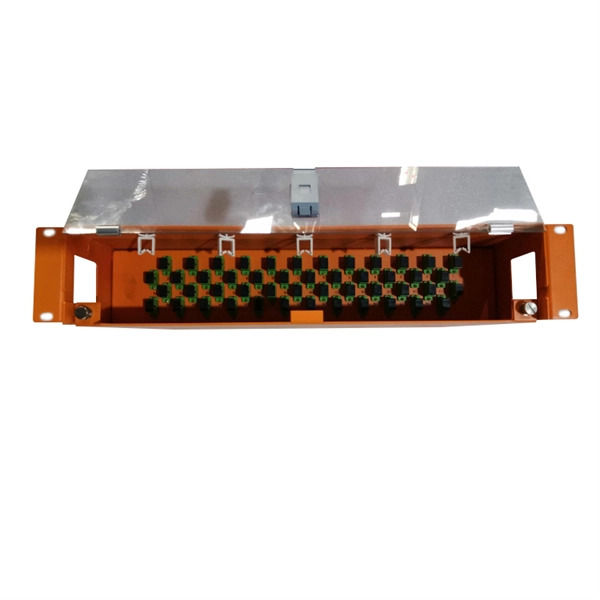
If you are ever in need of checking your ONT, this video will show you how to do so and what it is you are looking for. Always remember to securely close the box afterwards to prevent any damage to the facilities inside. more. A fiber termination box is the standard instrument used in fiber optic networks to connect, secure, and protect optical fibers at the terminating point. It functions as a junction between the incoming fiber cable and the outgoing customer-side fiber cable, where one fiber can be spliced, patched. Open the Fiber optic terminal box. Check and prepare installation tools and accessories. Prepare the cable according to the design. An ONT, or Optical Network Terminal, is the box where your fiber internet connection enters your home to power your fiber network. Your ONT is typically located in your garage, basement or outside your home within a few feet of your home's power box. It serves as a termination point for optical fibers, providing a secure and organized space for connecting and managing fiber optic cables. A fiber pigtail is a specific hardware connection used for cable termination. Proper installation and maintenance of FTBs are essential to ensure the reliability and performance of the network infrastructure.
[PDF]
Volume = 1 ton / 1 ton/m³ = 1 m³ For ton register (often used in shipping), the conversion is more straightforward. The formula is: Volume (m³) = Mass (ton reg) × 2. 83168466 This means that 1 ton register is equivalent to approximately 2. 83168466 cubic meters. So, for example:. The general formula for converting tons to cubic meters is: Volume (m³) = Mass (tons) / Density (tons/m³) This formula requires the density of the specific material in tons per cubic meter. For example, if you have the density of water (approximately 1 ton/m³), the conversion for 1 ton would yield:. Use this when purchase orders or shipping documents list weight in metric tons, but you need to estimate the space required in cubic meters. Convert metric tons to CBM using density so you can estimate freight volume and container requirements. Tons and cubic meters do not denote the same physical property – metric tons measure mass, while cubic meters measure volume. However, you can determine the amount of space a ton of a specific material fills by using the mass per volume of the substance, known as the density. Look up Density. The density of water is 1 t/m³, so 1 metric ton of water will occupy 1 cubic meter. 6008 m³ per US short ton. Purpose: It helps construction professionals and material handlers convert between weight and volume measurements for bulk materials.
[PDF]
The answer is yes, and it's a practice widely used in the industry to distribute signals to multiple destinations without degrading the signal quality significantly. This article delves into the methods, benefits, challenges, and practical applications of splitting fiber lines. A fiber optic splitter is a passive optical component that divides a single incoming optical signal into two or more outgoing signals, or combines multiple incoming signals into one. Its primary role is in Passive Optical Networks (PON), which are the foundation of. Fiber splitters are critical in optical networking, skillfully dividing a single light signal into multiple outputs for diverse applications. Their passive operation allows for widespread use in telecommunications, data distribution, and sensor systems, making them a backbone technology in. Power splitters (also commonly called “optical splitters”) are devices that divide an optical signal into multiple, equal-intensity output signals. The split ratios are usually even, like 1:2, 1:4, 1:8, and up to 1:32. Other split ratios are available, but usually come at a higher cost as they have. An optical splitter is a passive bidirectional element, which is used to connect a large number of subscribers/ONUs to an OLT. It is one of the most important elements of all FTTx PON and OLAN networks. What is Fiber Line.
[PDF]

In this step-by-step guide, we will walk you through the process, ensuring that you can seamlessly connect your optical cable and enjoy a clear and uninterrupted audiovisual experience. Optical cables are becoming increasingly popular for transmitting high-quality. Optical audio cables can easily improve your TV's sound by connecting to external speakers. Learning how to connect an optical cable is easy, but there are a couple of gotchas that you should know. Here are the basics: Identify the optical output; if there's a protective plastic cap, remove it. The most common types are: The Toslink optical cable is a standard for transmitting digital audio signals. It uses a plastic or glass fiber to carry light signals from one. You can connect an older flat screen TV to ANY Stereo system, Surround Sound system, or Soundbar. This video shows you step by step how to make audio connections using an digital optical cable. You can use an optical connection even if your audio system does not have an optical socket, and by using. One of the easiest ways to achieve high-quality sound is to connect your TV to a home theater system or soundbar. Easily connect your optical audio cable to your TV! Follow our step-by-step guide for a hassle-free setup and enjoy crystal-clear sound. No wonder how to improve TV sound, right? When the sound is weak, for example, when using an analog sound source, then an optical audio cable possibly will be the.
[PDF]

Attenuation describes the continuous loss along the fiber, while insertion loss describes the additional loss caused by components such as connectors, splices, or splitters. In fiber optic networks, particularly in FTTx (Fiber to the x) and PON (Passive Optical Networks) deployments, splitters play a central role in distributing the optical signal from a single source to multiple destinations. The split ratio and insertion loss are two key parameters defining their performance. A deeper understanding of these. This document describes how to calculate the maximum attenuation for an optical fiber. You can apply this methodology to all types of optical fibers in order to estimate the maximum distance that optical systems use. There are no specific requirements for this document. This document is not. By dividing a single optical signal from a central Optical Line Terminal (OLT) into multiple outputs for Optical Network Terminals (ONTs) at users' homes, splitters eliminate the need for dedicated fibers to each residence—slashing infrastructure costs while scaling network reach. Losses can be introduced by various means such as intrinsic material absorption, scattering, bending, connector loss and more. The tutorial has the following parts: When light propagates as a guided wave in a fiber core, it experiences some power losses. These are particularly important for long-haul data transmission through fiber-optic telecom.
[PDF]
With the large variety of beamsplitters available, the designer needs to take many factors into consideration. This article and its illustrations will go a long way toward making the correct choice less of a risk. All curves show typical performance. A beam splitter (or beamsplitter, power splitter) is an optical device which can split an incident light beam (e. a laser beam) into two (or sometimes more) beams, which may or may not have the same optical power (radiant flux). It is a crucial part of many optical experimental and measurement systems, such as interferometers, also finding widespread application in fibre optic telecommunications. One beam is typically reflected while the other is transmitted. Beamsplitters are often classified according to their construction: cube or plate. In this blog, we will explore the step-by-step process of using a beamsplitter cube effectively, along with some common applications that benefit from this powerful optical tool. Step-by-Step Guide on Using a Beamsplitter Cube Step 1: Understanding the Cube Orientation: A beamsplitter cube is a. A beam splitter is an optical device that splits beams (such as laser beams) into two (or more) beams. Beam splitters typically come in the form of a reflective device that can split beams into exactly 50/50, half of the beam being transmitted through the splitter and half being reflected.
[PDF]

The core measurement procedure follows five steps: Turn on the meter and let it warm up. Most meters need a brief stabilization period before readings are reliable. Check your model's manual, but a minute or two is typical. Set the wavelength to match your light source. Fiber loss is the difference between the power when light is coupled from the transmitting end to the fiber and the power when the light reaches the receiving end. Generally speaking, when measuring the. An optical power meter measures the strength of light traveling through a fiber optic cable, giving you a reading in dBm (decibels relative to one milliwatt). The basic process is straightforward: turn the meter on, set it to the correct wavelength, clean your connectors, plug in, and read the. A power meter and light source are essential test tools that work in tandem to measure fiber optic cable loss and evaluate the quality of optical links. They provide the data necessary to quantify signal loss and pinpoint issues that could impact network performance. Here's how they work: A power. You measure optical power in dBm or insertion loss in dB. Verify light travels from transmitter to receiver. We'll give you the basic information you need and provide some printable references.
[PDF]

This guide provides a complete framework for understanding, identifying, and planning MPO connector gender in data center environments. Visually, male and female MPO connectors are easy to distinguish: male connectors feature two alignment pins (PIN pins), while female connectors have corresponding holes instead of pins. An MPO connection is made between a male and female connector to make sure that there is proper alignment. Interfaces on active MPO equipment, such as transceivers are usually male, so any MPO trunk cable. In modern data centers and high-density fiber optic networks, MPO (Multi-Fiber Push-On) connectors have become an essential solution for achieving fast, reliable, and scalable connectivity. You will discover the physical distinctions between male and female connectors and how to develop a gender strategy for your infrastructure, which gender connects. Whether you're supporting parallel optics like 100G SR4 or densifying an optical distribution frame (ODF), MPO is now a cornerstone of network design. This article explains: And a practical checklist to design MPO systems that scale cleanly. If you only remember one thing: MPO is a multi-fiber. In MPO and MTP fiber connector systems, Male vs Female and Pin vs No-Pin describe the same core engineering attribute: the presence or absence of alignment pins on the MT ferrule. Unlike single-fiber connectors such as LC or SC, this distinction is not optional terminology but a mandatory.
[PDF]