In this comprehensive guide, we'll walk through the best practices for installing various types of fiber optic cable, from patch cords to distribution fiber, and provide practical tips to ensure a successful installation. The processes. Fiber optic installation delivers unmatched network performance for modern businesses, providing greater bandwidth capacity and superior resistance to electromagnetic interference compared to traditional copper cables. Professional installation ensures optimal performance and higher reliability for. In the spirit of self-reliance and technical mastery, we've crafted this detailed guide to empower you to take control of your own network by installing fiber optic cables yourself. In this guide, we will walk you through a step-by-step process for the installation of fiber optic cables. The number one cause of signal loss in optical fiber installations is dirt on. In this comprehensive guide, we'll cover everything you need to know about fiber optic cabling—from key components and installation procedures to best practices for network design and maintenance. What is Fiber Optic Cabling? Fiber optic cables transmit data as pulses of light through strands of.
[PDF]

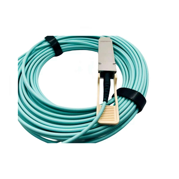
Connect the fiber optic cable: Attach the fiber optic cable's connector to the transceiver module on the switch. Make sure the connector type (e., SC, LC) matches the transceiver module. In addition, fiber cables can transmit data over several kilometers without signal degradation, making them ideal for connecting switches in large campus networks and between different buildings. As they do not emit electromagnetic signals, they're difficult to tap and secure against eavesdropping. Fiber optic cabling is increasingly used to connect network switches and other datacom equipment, especially in long-distance and mission-critical applications. Fiber provides: Increased internet signal bandwidth. Most modern fiber-enabled network switches require an SFP transceiver module. As we speak I just have optic fibre (Community Fibre) connected to my Huawei modem / Linksys Velop which will be connected to a new POE switch (need to identify the best model to be compatible with my optic fibre extension project). The objective is to run 1 or 2 additional optic fibre from the. Choose an SFP module based on the fiber optic cabling that will be connected to the network switches. SFP transceiver modules almost always require two fiber optic cable strands. Even the most advanced optical transceivers can only perform at their peak when paired with properly installed, clean, and precisely managed fiber.
[PDF]

Learn how to splice fiber optic cable using fusion splicing with this complete step-by-step guide. Includes tools, best practices, loss standards (ITU-T G. 652), cost analysis, and FAQs for network engineers and installers. 5,398 fiber splicing stock photos, vectors, and illustrations are available royalty-free for download. Template technician Fiberoptic Fusion Splicing. Worker connecting for Cable Internet signal and Wire connection with Fiber Optic Fusion Splicing machine,fiber optic cable splice machine in work. Splicing fiber optic cable is an extremely important phase for making dependable, high-speed communication infrastructures. Regardless of the type of fiber network you're deploying, be it for telecom, enterprise data centers, or smart city infrastructure, fusion splicing provides the benefits of. In this guide, we cover the basics of fiber optic splicing, how to perform splicing using two different methods, and finally some best practices to perform good fiber splicing. Ensure Your Splicing Tools are Clean – #2. For network managers and technicians, a poor splice can lead to significant signal degradation, network downtime, and costly troubleshooting. At Turn-Key. 🔧 Watch a real-time fiber optic splicing demo in action! In this step-by-step tutorial, learn how to splice fiber optic cables like a pro — perfect for telecom technicians, network engineers, and field techs.
[PDF]

This guide discusses common cable tray problems, from loosening and corrosion to grounding issues and installation errors, along with strategies for prevention and resolution. Understanding the root causes of cable tray failures is the first step toward ensuring system reliability. Let's delve into. How far apart should cable trays be supported? What's the risk if support spacing is too wide? Can I reconfigure tray layouts later? What's the best tray material for outdoor use? How can I reduce electromagnetic interference in trays? What are the common faults in cable? What is the most common. The products can be widely used in construction, energy, power, plant. There are five common ways to fix the cover plate of cable tray elbow supplier: pressing plate fixing, screwing fastening, clasping fixing, padlock fixing and seven-shaped buckle fixing. I would like to introduce to you the five. Steel cable trays form the backbone of organized and efficient electrical wiring in industrial, commercial and infrastructure projects. Whether installed as stainless steel cable trays, these components offer durable and flexible solutions for routing cables safely. However, like any other infrastructure, cable trays are prone to failures that can result in serious safety hazards, financial losses, and downtime. The specific operations are as.
[PDF]

How to hardwire a Self-Regulating heat cable into a junction box, with a tutorial of the final end seal. First thing, get the sealing ring and connect it onto the connector body. Make sure it gets onto the very e. Safety comes first, and clear info makes it doable. Know Your. We'll show you how to size the heater, run a new, safe 240-volt circuit and install a programmable thermostat. Most homes have sufficient capacity for the new circuit in the service. If you're working with heating cables, understanding how to connect them safely and efficiently is crucial. In this guide, we'll break down the steps in simple terms. Whether you're a DIY enthusiast or a professional, this article is here to help. Stay safe and ensure proper installation with these. I need help wiring an electric furnace with heat elements. I ran number 6 wire with ground from my 100 amp service box where I installed a 60amp double pole breaker. The furnace comes with an other set of breakers one 60amp and one. A distribution board or distribution box is where the main power supply is distributed to multiple loads. Single Phase Distribution Box generally consists of Double Pole MCBs, Single Pole MCBs, and RCCBs.
[PDF]
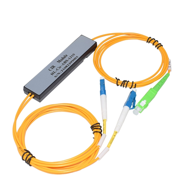
This guide demystifies fiber optic splitters, explaining their design, operating principles, types, key specifications, and real-world applications. Whether you're a network engineer designing a PON (Passive Optical Network) or a homeowner curious about how your fiber connection works. I'm planning to use a TP-Link MC220L transceiver to convert the optical signal to ethernet. This ethernet will then go through a 1 Gbit/s switch, and rout two ethernet cables to each floor. On each floor each ethernet cable will be connected to a router, which will then distribute the internet. DWDM/CWDM is like a two-edged sword. For a small fee (the procurement of the modules and the circulator) you can split/splice one physical fibre optic cable into multiple pairs. The downside is that once you loose your one-and-only fibre link (to a cable-hunting-buck-hoe) then you're in trouble. Fiber optic splitters enable the division of optical signals into multiple paths, allowing information to be distributed to multiple subscribers or devices simultaneously. Understanding the inner workings of fiber optic splitters is crucial for network administrators, technicians, and anyone. The answer is yes, and it's a practice widely used in the industry to distribute signals to multiple destinations without degrading the signal quality significantly. What is Fiber Line.
[PDF]
A 12-core ADSS cable for short spans (≤100 meters) might cost around $0. 35 per meter, using a standard double PE jacket and basic aramid strength members. Discover the latest ADSS fiber optic cable prices for various spans and core counts. Get competitive quotes, understand cost factors, and choose the best solution for your aerial fiber project. As global demand for faster and more reliable broadband expands, ADSS (All-Dielectric Self-Supporting). ADSS 24-wire anti-rodent type fiber optic cable, this design combines enhanced optical reliability with the highest degree of rodent resistance available in an all-dielectric cable. ADSS FRP Defender-Anti Rodent also can be used as an all-dielectric direct buried cable solution. Our team is. Fiber Optic Cable 258 Original Std ADSS Flex-Span ADSS New Std ADSS Applications • Electric utility transmission lines – Typically framed under conductors • EHV environments – Tracking-resistant options available Features • Up to 432 fibers in cable – Gel-Free Buffer Tube options available – up to.
[PDF]

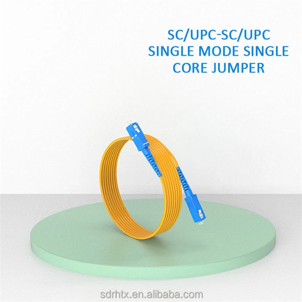
How to Terminate a Multi-mode Fiber Optic Cable with LC mechanical fast connectors. Fusion Splicer: For joining two fibers permanently by fusing them. Safety Equipment: Gloves and safety glasses are crucial to protect against the tiny glass shards of fiber optics. Adhere to industry standards such as. Here are the detailed epoxy LC connector assembly and termination instructions for both single mode and multimode LC connectors. The steps are pretty generic and are applicable to most major brands' LC connectors on the market, such as those from 3M, Seiko, Corning, Molex, AMP, etc. Here are the LC. We terminate fiber optic cable two ways - with connectors that can mate two fibers to create a temporary joint and/or connect the fiber to a piece of network gear or with splices which create a permanent joint between the two fibers. Inject glue Use special glue, insert the glue bottle from the tail handle, squeeze the glue bottle until glue overflows from the end of the ceramic ferrule. Remove the glue bottle and set the connector aside for later use. LC Multimode & Singlemode Connector Termination Instructions Put on safety glasses and prepare work area by organizing all necessary tools from the Fiber Termination Kit (P/N: FTERM-L2), LC Upgrade Kit (P/N: FTERM-LC) and the Consumables Kit (P/N: FT-CKIT-L2). Place primer bottle into primer stand.
[PDF]
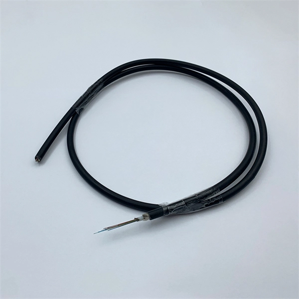
The typical thickness of a glass core can range anywhere from 8-10 um (microns) for single-mode and 62. 5-50 um for multimode; these core sizes are the most prevalent ones utilized in the telecommunications industry. The core of a conventional optical fiber is the part of the fiber that guides the light. It is a cylinder of glass or plastic that runs along the fiber's length. The core is surrounded by a medium with a lower index of refraction, typically a cladding of a different glass, or plastic. The light is transported along the optical fiber via its smallest and most crucial component, which is called the core. However, they are composed of many components, each constructed from advanced materials to guarantee the quick and reliable transmission of data. So, let's break it down! The core is the primary part of a Fiber optic cable. It's responsible for. The 8 Core Multimode Outdoor Fiber Optic Cable is designed for high-performance data transmission in various outdoor environments, making it an ideal choice for telecommunications, networking, and data center applications. We supply single mode GYTS fiber optical cable and multimode GYTS fiber optic cable, fiber strand from 2 cores to 432 cores. A related GYTA type cable is available. This advanced cabling solution allows fast, secure data transfer and telecom over long distances. Understanding the components within a fiber optic cable enables.
[PDF]
Step-by-step on-site guide: learn how to plan, mark, support, and install cable trays correctly, from shop drawing approval to final checks. Method Statement installation of Cable Trays and Ladders - Planning Engineer FZE. The Cable Tray system is installed in electrical rooms, plant rooms, and service. Whether you're building a commercial setup or upgrading an industrial plant, proper cable tray installation ensures neat wiring, safe access, and easy maintenance. But before you lay the first tray or clamp down a single cable, you need a solid plan. This guide breaks down the process step by step. In order to get it right, installers are supposed to adhere to a plan that ensures that wires are kept cool and the building is stable. The beginning of success is to review the Bill of Quantities (BOQ) so that. In this post, we will see together how to install cable tray on-site. Firstly, we need an approved shop drawing that shows the cable tray route, its dimensions, installation height, support system, the number of layers of these trays, and the type of systems they will serve. The key requirements for cable tray installation include: Incorrect installation can lead to overheating, cable damage, or system failure. This guide covers the critical steps, from selecting the right electrical cable tray and performing accurate cable fill.
[PDF]
In part two of the 7-part series on how to wire a switch, I explain and demonstrate how to install the cables into a multi-gang box. The video focuses on steps that will both save time and simplify the process. In this video, we'll walk you through the process of wiring a home distribution box with a detailed connection diagram. Whether you're an electrician or a DIY enthusiast, this guide will help you understand the basics of home electrical distribution. Part of my job as a professional electrician is keeping my work neat and organized. A tidy work box makes it easier to install lights, switches, and outlets, and it helps future electricians to see what's going on inside the. Learn how to install a distribution box safely and correctly. Covers wiring, placement, standards, and expert tips for a compliant setup. A distribution box is the heart of any electrical system. It takes the incoming power and safely distributes it to different circuits throughout your building. If you're looking to install a switch box in your home or office, it's important to understand the process involved and the key steps to follow. And all the switching and protective devices are installed in the. According to NEC (National Electric Code: Article 1 00-Definitions), a Main Panel (also known as Panelboard, load center, breaker box and distribution board etc. ) is a cabinet or cutout box which contains on controlling and protective devices (such as circuit breakers, fuses, switches etc.
[PDF]

This visualization shows the growth of the undersea cable network, global internet peering capacity, and the distribution of IP addresses via BGP announcements over time. Use the controls at the top to play the animation or step through year by year. The Submarine Cable Map is a free and regularly updated resource from TeleGeography. TeleGeography's comprehensive and regularly updated interactive map of the world's major submarine cable systems and landing stations. For more details and insights, please read this. Dongguan TW-SCIE Co.,Ltd is a professional manufacturer of FTTH drop cable, indoor/ outdoor fiber optic cable and patch cord. Products are conform to ISO 9001 standard. Welcome to visit us: Krasnopresnenskaya Naberezhnaya, 14. Dongguan Guanhong Optical Cable Co., Ltd (referred as Fiberplan) is a high-tech enterprise integrating the research, manufacture and marketing. And we can produce customized products as customer's require. The facility commenced operations in 2003, and its purpose was publicly revealed by AT&T technician Mark Klein in 2006. Room 641A is located in the SBC Communications building at 611 Folsom Street, San Francisco, three floors of which were occupied by AT&T before SBC purchased AT&T.
[PDF]

Arduino-Powered Data Transmission with Fiber Optics Welcome to our video tutorial on optical communication with Arduino, designed to be easy t. more. They consist of a transmitter on one end of a fiber and a receiver on the other end. Most systems use a "transceiver" which includes both transmission and. I'm going to use HFBR 1414 fiber optic transmitter module which is manufactured by Broadcom. It is a low-cost high-power transmitter that is designed for use in industrial power generation, power distribution, medical transportation and gaming applications. Internally, the optical fiber consists of a highly reflective central core, which acts like a light guide. Media converters are special fiber optic transceivers used to convert from one type of cable (the media) to another, typically from copper cables to fiber optics, although some media converters will convert from one fiber type to another, e. multimode to singlemode. The FOA Guide has a page about. A fiber optic transceiver (also called an optical transceiver) is a compact module that both transmits and receives data signals through optical fibers. It serves a dual purpose — transmitting electrical signals as light pulses and receiving light pulses to convert them back into electrical form.
[PDF]
The formula to calculate the cable tray capacity is: [ CTC = text {floor}left (frac {W cdot H cdot FR} {CA}right) ] Where: ( CTC ) is the cable tray capacity (number of cables). ( W ) is the width of the cable tray (inches). ( H ) is the height of. This calculator determines the maximum number of cables that can be safely housed within a cable tray based on its dimensions and the cross-sectional area of the cables. Properly calculating cable tray capacity is crucial for ensuring efficient airflow, preventing overheating, and maintaining. Calculate the appropriate cable tray size based on your cables and fill requirements. This calculator determines if your tray meets industry standards (typically 30-50% fill for alternating single-layer or 40-50% for random arrangement). ( FR. The right cable tray sizing calculator helps engineers turn cable schedules into a verified tray width and fill check before material ordering and site installation. IEC 61537 covers cable tray and cable ladder systems for the support and accommodation of cables, while NEC Article 392 governs cable. In practice, cable tray dimensions are a system of interrelated measurements —width, depth, length, and material thickness—that directly affect cable fill compliance, heat dissipation, structural loading, and long-term expandability.
[PDF]

Learn how to safely wire a single-pole (one way) light switch in this beginner-friendly tutorial. Whether you're replacing an old switch or doing your first DIY electrical project, this guide will walk you through every step — no experience needed!. more. This page contains wiring diagrams for household light switches and includes: a switch loop, single-pole switches, light dimmer, and a few choices for wiring an outlet/switch combo device. That's because virtually all light switches that control 120-volt fixtures are single-pole switches. Most light switches are also single-throw, which. Summary: Fully explained wiring diagrams and photos show how to wire switches including: single switches, 3-way switches, 4-way switches, and dimmer switches. and Be Sure to Subscribe! Make sure the circuit power has been turned off, and mark the circuit breaker or fuse to indicate that work is. A distribution board or distribution box is where the main power supply is distributed to multiple loads. And all the switching and protective devices are installed in the distribution box. Single Phase Distribution Box generally consists of Double Pole MCBs, Single Pole MCBs, and RCCBs. Wiring a single light switch may seem like a daunting task, but with the right tools, a bit of patience, and this comprehensive guide, you'll be able to tackle this DIY project with confidence. Remember, while this guide provides detailed instructions, always prioritize safety and consult a.
[PDF]