
If you find there is no ground wire in your electrical system, consider replacing outdated two-prong outlets, installing Ground Fault Circuit Interrupters (GFCIs), or exploring grounding through metal conduit or armored cable. Electrical grounding is a fundamental safety mechanism that provides a low-resistance route for fault current to return to the source and trip a circuit breaker or fuse. This pathway prevents metal casings of appliances and tools from becoming energized with hazardous voltage during an internal. It's possible that there's a ground wire that's connected to the box, but if this is original 1948 wiring, that's unlikely. If there's been a wiring update since, it's possible. As noted above, a GFCI receptacle is now required in the kitchen and installing them adds protection even if they're not. A ground wire can be connected to an electrical junction box if no place is available for its attachment. It is extremely important not to cut the ground wire. In this comprehensive guide, we will walk you through the steps to. If you cannot find a ground wire, use this instruction to add one to the panel. The process involves the following: 1). Therefore, before installing the ground wire, you should first plant the rod. You only need three. Is it OK not to connect the ground wire? It is entirely possible for an electrical device to not use the ground. Especially for low-power devices, such as routers, mobile phone chargers, small lamps, and so on.
[PDF]
In this guide, we break down the two core stages of optical fiber manufacturing: preform production (shaping the precursor material) and fiber drawing (transforming the preform into thin, usable fiber). Explore the optical cable manufacturing process. Learn about raw materials, fiber drawing, cabling, and quality control in modern optical cable manufacturing. Is your digital life lagging? Slow streams, dropped calls? The unsung hero of our connected world, the optical cable, might be the key, and. Fiber optic cables are the backbone of today's high-speed internet, telecommunication systems, and data transfer technologies. Fiber optic technology has revolutionized the way information is transmitted, offering numerous advantages over traditional copper wiring. What makes fiber optic cables special is their ability to. The production of optical fiber is a precision-driven process that transforms raw materials like silicon tetrachloride into ultra-thin, high-performance fibers capable of transmitting terabits of data over thousands of kilometers. This manufacturing journey directly impacts the fiber's mechanical.
[PDF]

In this video, we'll show you how to connect an energy meter to a distribution board (DB) safely and efficiently. energy meter connection with distribution box How to Connect an Energy Meter to Your Distribution Box Easily Steps to Properly Connect Your Energy Meter to a Distribution Box. It plays a vital role in ensuring the safe and efficient distribution of electricity throughout the premises. What is the wire from the meter to the breaker box? Also. Always begin with disconnecting the main supply before accessing any enclosure containing distribution components. This prevents arc faults and ensures safety when modifying or inspecting current paths. This “meter to panel” wiring establishes the pathway for all incoming electrical power from the grid to the home. Its primary function is to safely and reliably. Distribution Board aslo know as “Panel Board”, “Switch & Fuse Board” or “Consumer Unit” is a box installed in the building containing on protective devices, such as circuit breaker, fuses, isolator, switches, RCDs and MCBs etc. The electric main supply (230V AC & 120V AC in US) is connected through. Changed Texas's reference diagram for the 3 wire network 120/208 Volt single phase self-contained Revised Figures 13, 14, 14b. Limited the meter location from pad mount transformer for PSO. Removed unistrut being listed as an alternative means for mounting the meter box. APCo and TX do not allow.
[PDF]

In today's video, we'll be unboxing the 9-Port Power Supply Box and demonstrating how to connect the cables to provide power to CCTV cameras. A CCTV power supply box sends power to all your cameras from one place. It helps keep things neat and makes your system easier to manage. In this guide, you'll learn how to install it step by step, choose the right type, avoid common problems, and keep your system running safely. Power supply boxes for CCTV are typically used in multi-camera installations instead of using single power adapters for each camera. The process is almost exactly the same if you. Installers of surveillance systems may simply control the power to various CCTV cameras using a CCTV power supply box, also known as a power distribution box (usually at the location of the DVR). This enables a cleaner camera installation. Surge protection can be accomplished in two ways. The power supply box is specifically used to transfer power requirements for all cameras plugged in on the system, to work. Security cameras use RG59U coax siamese wire or CAT5e networking cable to transmit video. Whether you are installing a power box for a new or existing camera system, it is important to understand how to connect cameras to a CCTV Power Supply Box. DC current is polarized meaning it has two leads, a.
[PDF]

How to Use Optical Power Meter TR-504 | Optical Power Meter Working| Testing OPM, VFL, RJ45 | TRICOM In this video, we walk you through how to use the TRICOM TR-504 Optical Power Meter and explain how it works. Learn how to test fiber optic cables, OPM, VFL . Optical power meters are a key element in the optimization and maintenance of such optical networks and of their components. In this article, learn: What is an optical power meter? An optical power meter (OPM) measures the power levels of light signals in devices that transmit data or power using. An optical power meter measures the strength of light traveling through a fiber optic cable, giving you a reading in dBm (decibels relative to one milliwatt). The basic process is straightforward: turn the meter on, set it to the correct wavelength, clean your connectors, plug in, and read the. OPM interface: insert the fiber to be tested, test the optical power. An optical power meter is a tool that measures the number of optical power in a cable is fiber-optic. It helps engineers verify the performance of optical fiber systems, ensuring that the signal strength meets requirements, and is an essential tool for communication network maintenance and troubleshooting.
[PDF]

To use a power meter for fiber optic testing, always clean connectors first with lint-free wipes or click-to-clean tools. Select the correct wavelength and set your reference. You measure optical power in dBm or insertion loss in dB. Consistent procedures ensure accuracy. Verify light travels from. The most basic fiber optic measurement is optical power from the end of a fiber. This measurement is the basis for loss measurements as well as the power from a source or presented at a receiver. Typically both transmitters and receivers have receptacles for fiber optic connectors, so measuring the. An optical power meter measures the strength of light traveling through a fiber optic cable, giving you a reading in dBm (decibels relative to one milliwatt). This article will guide you through the methods, instruments, and key considerations for measuring fiber. Fiber optic cabling is the high-performance core of today's datacom networks. As network speeds and bandwidth demands increase, fiber performance requirements have become more stringent. Fiber testing is more important than ever. An OPM uses a photodiode to generate an electrical current proportional to optical power.
[PDF]

By operating from a single 2. 5V input power rail and integrating the controller, gate driver, power inductor, and MOSFETs, these mini modules are optimized for space-constrained applications like optical modules, wearables, IoT, networking. SFP (Small Form-factor Pluggable) optical modules are compact, hot-pluggable transceivers that enable network equipment to connect seamlessly to fiber and copper links. These modules, including SFP, SFP+, and SFP28, are widely used in enterprise networks, data centers, and carrier-grade deployments. The optical module serves as a crucial component in optical fiber communication systems, operating at the physical layer, which is the lowest layer in the OSI model. Its primary function is to achieve optoelectronic conversion by converting electrical signals into optical signals and vice versa. Think of it as the “translator” for your network equipment, converting electrical signals into optical signals. As an essential component of optical fiber communication, optical modules are optoelectronic devices that facilitate the conversion between optical and electrical signals during the transmission process. They are essential in applications like telecommunications, data centers, and enterprise networks. Optoelectronic devices have transmitting and receiving modes.
[PDF]

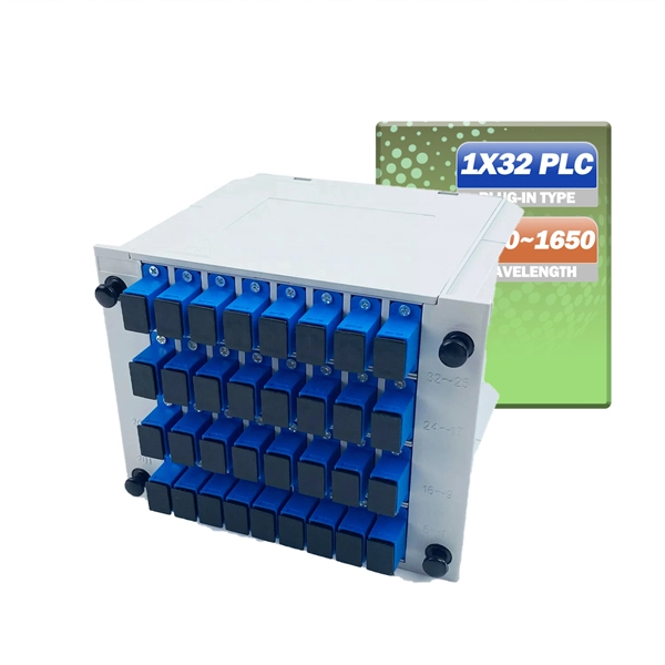
In this beginner-friendly guide, we'll explain what it is, why the “APC” matters, the different types you can buy, how to select the right model, and how to install and test it correctly. What is an SC/APC Fiber Optic Adapter?. Fiber optic adapters, also known as couplers, play a crucial role in fiber optic networks by providing a connection point between two fiber optic connectors. They enable seamless and reliable optical signal transmission between different fiber optic cables, connectors, or devices. Using the wrong type or neglecting cleaning can lead to signal loss and unstable connections. This guide covers adapter types, selection criteria, cleaning tips, FAQs, and B2B customization options to help businesses build reliable and scalable fiber networks. It ensures precise alignment between fibers and facilitates effective transmission of optical signals. Without the proper adapter, signals can degrade or become unstable, which can dramatically decrease the reliability of a network.
[PDF]

Instead of relying on assumptions, this guide offers a clear-eyed look at how to properly secure your fiber infrastructure, moving beyond the myths to implement practical, layered defenses that provide real-world protection for your organization's most sensitive data. For manufacturers and industry professionals involved in creating, deploying, or maintaining these critical systems, ensuring the robust and reliable securement of fiber optic cables is paramount. “Securing” fiber optic cable goes beyond just preventing it from moving; it encompasses protecting its. Fiber optic cables enable high-speed, long-distance data transfer, forming the backbone of modern communication. Yet, outdoors, they face temperature swings, moisture, UV exposure, rodents, and human interference. Protecting them is essential for long-term reliability. This guide covers how to. Fiber optic and ACSR (Aluminum Conductor Steel Reinforced) cables play a critical role in modern infrastructure, including power transmission and telecommunications. However, these cables face several challenges that can compromise their performance and longevity. If you are an optical engineer or a fiber optic network operator, you need to know how to protect your cables from these threats and ensure. An effective fiber optic network security plan acknowledges these potential weak spots and addresses them head-on. Before beginning any installation, safety.
[PDF]

A neat, well-organized subpanel bundles wires to conserve space and improve access. Ideally, wire groups are installed in layers and wires are bent at right angles to buses or breakers. Label short sheathing sections (slugs) to indicate which circuits wires serve. We cover everything from separating color-coded wires and securing them with ties to. Discover 7 DIY tips to organize your electrical panel for improved safety, easier troubleshooting, and efficient maintenance. Prevent hazards while making your home's electrical system more manageable. A disorganized electrical panel isn't just an eyesore—it's a safety hazard and troubleshooting. According to NEC (National Electric Code: Article 1 00-Definitions), a Main Panel (also known as Panelboard, load center, breaker box and distribution board etc. ) is a cabinet or cutout box which contains on controlling and protective devices (such as circuit breakers, fuses, switches etc. ) used to. Welcome to this live training session! ⚡ In today's tutorial, I'll be demonstrating how to arrange cables neatly inside a distribution bo. more See what others said about this video while it was live. If you're struggling with unsightly cords hanging around your cabinets, worry not! In this guide, we'll explore practical strategies to conceal those wires effectively. Before starting the process of.
[PDF]
The per-unit ranges commonly appear as $1,000-$2,500 per major component (panel or service upgrade) and $2-$8 per linear foot for wiring, depending on accessibility and installation complexity. The current total tariff rate on Electrical Wiring & Conduit from Tajikistan is 19. This is composed of the following layers: MFN base rate: 4. 5%; Section 122 surcharge: 15%. How much will it cost to import Electrical Wiring & Conduit from. What type of plugs and sockets are used in Tajikistan? When you are going on a trip to Tajikistan, be sure to pack the appropriate travel plug adapter that fits the local sockets. But what do those electrical outlets look like? In Tajikistan, types C and F are the official standards. 67 times less expensive than the world average. Tajikistan ranked 150th out of 197 countries by cost of living and the 153rd best country to live in. The average salary after taxes in Tajikistan is $216, which is enough to cover living expenses. Typical total project ranges for a residential electrical upgrade are $2,500-$8,000, with larger full-panel or service-upgrade jobs running $6,000-$15,000 in some markets. Get free. Brilltech Engineers Pvt. Ltd is the one you can reach. We have a highly experienced team, well-loaded manufacturing unit and a lot more to match up the ever-evolving needs of our customers. Moreover, our focus on maintaining high quality and attaining customer satisfaction stands us ahead of the.
[PDF]

In this video, we'll walk you through the process of resurrecting y. The test sets display a laser warning icon when the laser source is active to alert the user about a potentially dangerous situation. It is recommended to: Deactivate the laser before connecting or disconnecting optical cables or patchcords. more Is your optical power meter showing no signs of life? Don't worry; we've got you covered! In. Introduction The RP460 Optical Power Meter is an ultra low cost, and compact power meter used for verifying both absolute and relative power across any given fiber. This document will serve as an overview of the major features and functions of the device and will offer tips for trouble shooting. Fiber Optical Powermeter User Manual | FS Title Author Subject Keywords Created Date. The OPM1315 is a newly developed portable optical power meter. It is equipped with a 1. 0 mm large area detector so that stability and reliability can be enhanced effectively. This unit is designed to fit the hand comfortably, and can be used for installation, debugging, and maintenance of any fiber. ments to the instrument's performance and functionality. The figures given in this manual ion of this manual to ensure the accuracy of its contents. However, should you have any questions or fi gistered users with a variety of information and services. Please allow us to serve you best by.
[PDF]

In this complete wiring diagram guide, we will walk you through the step-by-step process of wiring a mag starter. We will explain the purpose and function of each component, provide clear diagrams, and offer expert tips to ensure a successful installation. Whether you're a beginner or an. For proper integration of an electromagnetic securing device, ensure the power supply matches the specified voltage–typically 12V or 24V DC. Incorrect voltage can cause malfunction or reduced holding force. Use a regulated power source to prevent current fluctuations that might trigger false alarms. Understanding the wiring diagram of a magnetic starter is essential for technicians and electricians who work with electric motors. This diagram provides a visual representation of the components and connections involved in the operation of the starter. Once you have everything ready, you can proceed with the installation process. Begin by determining the appropriate position for the magnetic lock on the door. Quick guide on how to wire an access control system with power supply, lock, and exit button. more Quick guide on how to wire an access control. Installing a magnetic door lock can be a cost-effective and reliable way to secure your doors. These locks use an electromagnetic current to keep the door securely closed, and they are commonly used in commercial and residential buildings.
[PDF]

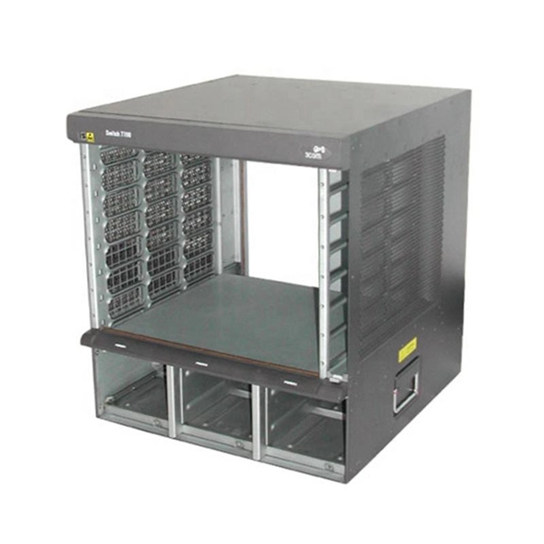
This section includes all PoE enabled Industrial switches available, including managed models and specific application models like vehicle or substation compliant units. Check each product page for other buying options. Shop products from small business brands sold in Amazon's store. Learn more Need help? Industrial-grade PoE switches for demanding. POE Industrial Ethernet units at Plant Technology USA make Power over Ethernet solutions even more efficient and cost effective. Not only are these de. Read more Find the best Industrial Ethernet Equipment for your project. US-based Customer Support. These rugged, fanless platforms support both Gigabit and 10/100 Mbps Ethernet and offer a selection of fixed-fiber, or SFP uplink. We provide a wide range of PoE/PoE+/PoE++ switches with up to 90 W output per port to deliver high-speed data transmission while powering high-power devices over long distances. With an industrial-grade design, our PoE switches provide surge protection of 4 kV per LAN port. Additionally, Smart PoE. In addition to transmitting network data, a PoE Switch has a built-in Power over Ethernet injector to supply up to 100W Power over Ethernet (PoE) to standards-based 802. 3bt compliant devices such as IP cameras, VoIP phones, and wireless access points. When connecting network.
[PDF]
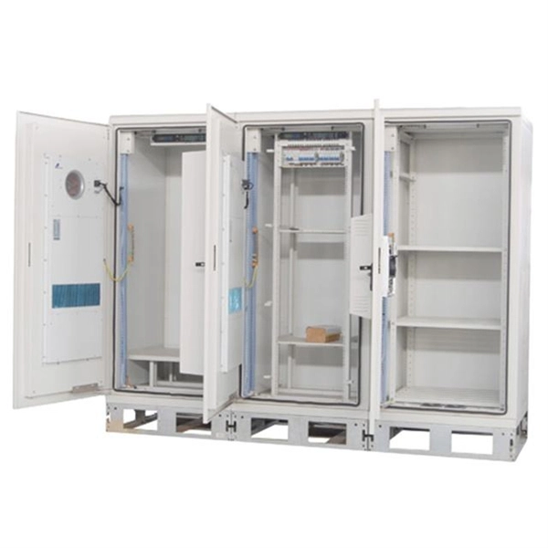
Here you can download the program for the configuration of our electrical cabinets. Written by Schneider Electric's most talented electrical distribution experts, the Electrical Installation Guide is written for professionals who design, install, inspect, and maintain low-voltage electrical installations in compliance with the standards published by the International. Perhaps you need to minimise heat losses to air in a facility without air-conditioning? Many of our most popular DC and AC power systems can be built into IP54 cabinets. An IP54 level of Ingress Protection provides a high level of protection against non-conductive airborne pollutants. Used to house electrical or electronic switchgear, control gear and equipment. The PDU series is designed to meet the needs of power distribution units of telecom access sites. It comes with an integrated controller that enables customer to read tenant-wise energy statistics as well as to extend the remote monitoring access. It is flexible enough to mount in the different. This Electrical Installation Wiki is a collaborative platform, brought to you by Schneider Electric: our experts are continuously improving its content, collaboration is also open to all. DC power is typically used in Data Centres and telecom facilities as it has several benefits. Firstly, DC power can be more efficient than AC power systems as the need for AC to DC conversion is.
[PDF]