This guide provides instruction on how to install and configure your MS130R series switch. For more switch installation guides, refer to the switch installation guides section on. This guide provides step-by-step instructions for installing two common types of industrial switches: rack-mount, and DIN-rail switches. Choose the Installation Location: Select an appropriate spot on the DIN rail for mounting. This chapter describes how to start your switch and how to interpret the power-on self-test (POST) that ensures proper operation. No prior experience needed—just follow along and you'll have your switch installed and running in minutes. more In this video you'll see a complete, step-by-step guide to mounting. This typeface indicates command syntax, or represents information as it is displayed on the screen. When you see the word enter in this guide, you must type something, and then press the Return or Enter key. Do not press the Return or Enter key when an instruction simply says type. Here, we explore the four most common installation methods for industrial switches: Desktop installation is the most straightforward approach— placing the switch like a small box directly on a table, control panel surface, or equipment rack without extra fixtures. Simple setup: No tools required.
[PDF]
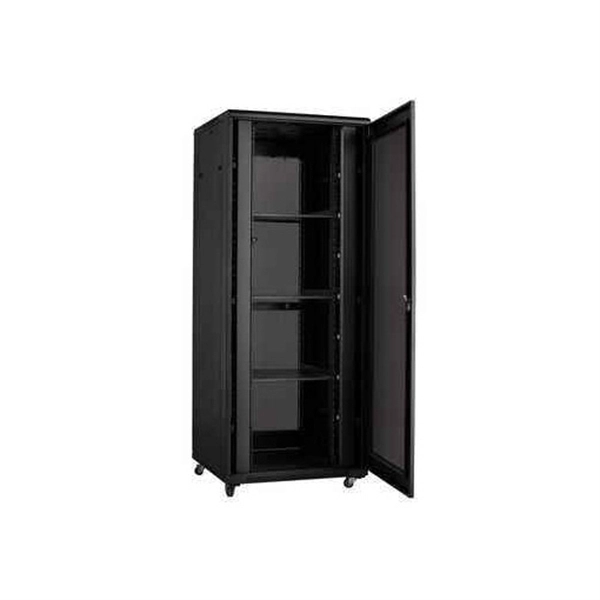
Encuentra opciones de almacenamiento y organización en Gabinetes, Racks Servidores y Sistemas de Cableado Estructurado para Redes de Voz y Datos de calidad. Optimiza tu red en Costa Rica. DURABLE - Crafted from cold-rolled steel with a protective black powder coating, the 6U NavePoint Performance Series network cabinet provides sturdy, reliable housing for network and server equipment. Capable of supporting up to 130 lbs, it's an ideal, durable solution for installers working on. TecnoBonilla. com es la mejor fuente para Rack Servers en Costa Rica. Para más información, póngase en contacto con nosotros en 6286-7654.
[PDF]
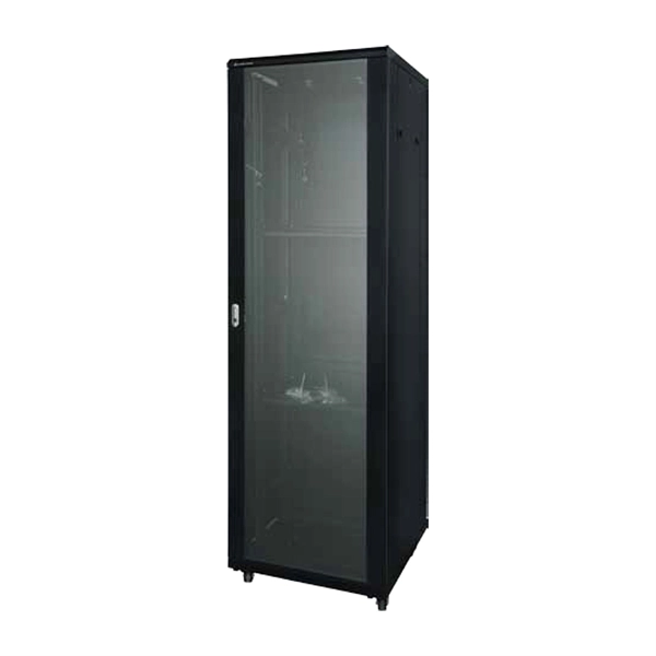
Rack height is measured in rack units (U), where 1U equals 1. Common rack formats include: 24U and below — typical for branch offices or small server rooms. Below is a comprehensive, fully detailed guide covering all standard server rack sizes, form factors, height considerations, depth classifications, and best-practice configuration approaches for professional environments. What Is a Server Rack? Understanding the Core Structure A server rack is a. This comprehensive blog post demystifies the "U" unit in network server accessories—the standard measurement that defines the height of equipment in server racks. A 2U server occupies two rack units, while a 4U server takes up four. Each rack is equipped with mounting rails. A “Rack Unit” (U) is a standard height measure for mounting equipment in a server rack. This article explains definition, planning, installation tips, and trends. At Secure Gates Inc., we provide high-quality 6U, 9U, and 12U Network Rack Cabinets designed to meet the unique needs of professionals, businesses, and data centers. In this blog post, we'll explore what network rack cabinets are, their key benefits, and help you decide which size— 6U, 9U, or 12U. U (rack unit, RU) is a unit of equipment height in a 19" rack. Important: U describes height only, but a server's real "capabilities" are also determined by chassis depth, internal layout, airflow, rails, power, and expansion (PCIe/risers, NVMe.
[PDF]

To use a power meter for fiber optic testing, always clean connectors first with lint-free wipes or click-to-clean tools. Select the correct wavelength and set your reference. You measure optical power in dBm or insertion loss in dB. Consistent procedures ensure accuracy. Verify light travels from. The most basic fiber optic measurement is optical power from the end of a fiber. This measurement is the basis for loss measurements as well as the power from a source or presented at a receiver. Typically both transmitters and receivers have receptacles for fiber optic connectors, so measuring the. An optical power meter measures the strength of light traveling through a fiber optic cable, giving you a reading in dBm (decibels relative to one milliwatt). This article will guide you through the methods, instruments, and key considerations for measuring fiber. Fiber optic cabling is the high-performance core of today's datacom networks. As network speeds and bandwidth demands increase, fiber performance requirements have become more stringent. Fiber testing is more important than ever. An OPM uses a photodiode to generate an electrical current proportional to optical power.
[PDF]

While optical power meters are the primary power measurement instrument, optical loss test sets (OLTSs) and optical time domain reflectometers (OTDRs) also measure power in testing loss. TIA standard test FOTP-95 covers the measurement of optical power. This measurement is the basis for loss measurements as well as the power from a source or presented at a receiver. Typically both transmitters and receivers have receptacles for fiber optic connectors, so measuring the. You need a power meter to measure power in a fiber optic system; most power meters come with a screw-on-adapter that matches the connector being tested and a little aid from the network electronics to turn on the transmitter. During the measurement of power, the meter must be set to the proper. Fluke Networks sets the standard in network testing with its advanced range of fiber optic power meters and fault locators, designed to ensure the highest precision in fiber optic meter readings and power evaluations. This is measured in decibels (dB). Splitters, fusion splices, connectors and. To use a power meter for fiber optic testing, always clean connectors first with lint-free wipes or click-to-clean tools. Select the correct wavelength and set your reference. Consistent procedures ensure accuracy.
[PDF]

The first thing you should do is locate the fiber optic cable that comes from the service provider. Once inserted, make sure it is securely. However, setting up a fiber optic connection to your router can seem daunting if you're unfamiliar with the process. Why Use Fiber Optic Internet? Before diving into the setup, let's quickly. Ensure your fiber optic router has an available WAN (Wide Area Network) or Ethernet port for the fiber optic modem. It's thin, flexible, and usually comes with connectors on both ends. Power Cables: Get power cables for both the. The fiber optic cable does not plug directly into a standard home router because the signal type must be translated. The fiber line terminates at the Optical Network Terminal (ONT), which is typically supplied and installed by the internet service provider. This specialized equipment serves as the. The process to connect fiber optic cable to router requires careful attention to detail, but I'll walk you through every critical step with the precision and clarity you deserve. Here's a step-by-step guide to help you through it. Understand the Basics Before diving in, familiarize yourself with the components involved:. Follow along as we take you through the step-by-step process of installing fiber internet! From preparing the site to connecting the final cables, we'll show you what goes into bringing high-speed internet to your doorstep. Whether you're a tech enthusiast or just curious about how it all w.
[PDF]

Check the electrical load and ensure that the sensors do not exceed the 10 Amp maximum. Check each wire for damage that may lead to a short. Check the tightness of electrical connections along the power. Issue: Frequent tripping of circuit breakers is one of the most common issues in distribution boards. It can occur due to overloaded circuits, short circuits, or ground faults. Solution: Identify the Cause: Check if the breaker is tripping due to overloading. Internal Inspection Open the distribution box and check for dust and debris accumulation. Inspect circuit breakers for proper operation. Ensure all connections are tight and secure. Each circuit breaker protects a specific circuit in your home, preventing excessive current from damaging wiring and. MDB is panel under power distribution system which consists of a fuse, circuit breakers and ground leakage protection units. Where electrical energy is taken from a transformer or an upstream panel to distribute electrical power to numerous individual circuits or consumer points. Various types of panels exist in every electrical.
[PDF]

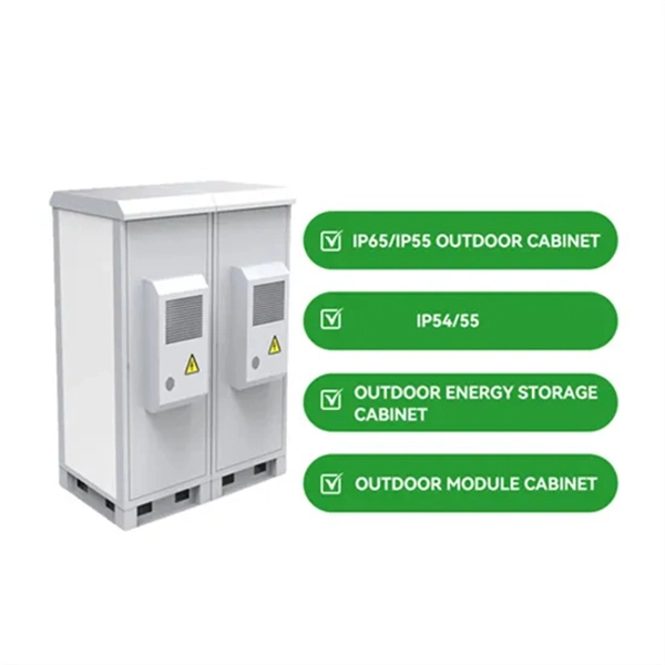
The typical setup time for a standard rapid deployment telecom tower ranges from 15 to 60 minutes once the unit arrives on site. However, complex installations requiring guy wires, heavy payloads, or difficult terrain can extend this window to 2-4 hours. How Should You Prepare for Installing Fiber Optic Internet? Before installing fiber optic internet, ensure your business location is ready. Site Planning and Design: This phase involves assessing the need for a new mobile site, selecting a suitable location, and designing the layout of the infrastructure. Conduct radio frequency (RF) planning and coverage analysis to determine areas with poor or no signal. Analyze user demand and. Equipment installation: Once the site is prepared, the equipment can be installed. This includes installing the telecom equipment in the cabinets, setting up the antennas, and running the cables. Testing and commissioning: Once the equipment is installed, it needs to be tested and commissioned to. Assuming the design is completed, we're looking at the process of physically installing and completing the network, turning the design into an operating system. Since. How long does it take to install fiber optic internet? The time it takes to install fiber optic internet depends on your home's layout and existing infrastructure. Will the technician dig up my yard to install fiber optic internet? Your fiber technician will need to either bury the fiber in your.
[PDF]

In this video, we'll show you how to connect an energy meter to a distribution board (DB) safely and efficiently. energy meter connection with distribution box How to Connect an Energy Meter to Your Distribution Box Easily Steps to Properly Connect Your Energy Meter to a Distribution Box. It plays a vital role in ensuring the safe and efficient distribution of electricity throughout the premises. What is the wire from the meter to the breaker box? Also. Always begin with disconnecting the main supply before accessing any enclosure containing distribution components. This prevents arc faults and ensures safety when modifying or inspecting current paths. This “meter to panel” wiring establishes the pathway for all incoming electrical power from the grid to the home. Its primary function is to safely and reliably. Distribution Board aslo know as “Panel Board”, “Switch & Fuse Board” or “Consumer Unit” is a box installed in the building containing on protective devices, such as circuit breaker, fuses, isolator, switches, RCDs and MCBs etc. The electric main supply (230V AC & 120V AC in US) is connected through. Changed Texas's reference diagram for the 3 wire network 120/208 Volt single phase self-contained Revised Figures 13, 14, 14b. Limited the meter location from pad mount transformer for PSO. Removed unistrut being listed as an alternative means for mounting the meter box. APCo and TX do not allow.
[PDF]

A neat, well-organized subpanel bundles wires to conserve space and improve access. Ideally, wire groups are installed in layers and wires are bent at right angles to buses or breakers. Label short sheathing sections (slugs) to indicate which circuits wires serve. We cover everything from separating color-coded wires and securing them with ties to. Discover 7 DIY tips to organize your electrical panel for improved safety, easier troubleshooting, and efficient maintenance. Prevent hazards while making your home's electrical system more manageable. A disorganized electrical panel isn't just an eyesore—it's a safety hazard and troubleshooting. According to NEC (National Electric Code: Article 1 00-Definitions), a Main Panel (also known as Panelboard, load center, breaker box and distribution board etc. ) is a cabinet or cutout box which contains on controlling and protective devices (such as circuit breakers, fuses, switches etc. ) used to. Welcome to this live training session! ⚡ In today's tutorial, I'll be demonstrating how to arrange cables neatly inside a distribution bo. more See what others said about this video while it was live. If you're struggling with unsightly cords hanging around your cabinets, worry not! In this guide, we'll explore practical strategies to conceal those wires effectively. Before starting the process of.
[PDF]

Instead of relying on assumptions, this guide offers a clear-eyed look at how to properly secure your fiber infrastructure, moving beyond the myths to implement practical, layered defenses that provide real-world protection for your organization's most sensitive data. For manufacturers and industry professionals involved in creating, deploying, or maintaining these critical systems, ensuring the robust and reliable securement of fiber optic cables is paramount. “Securing” fiber optic cable goes beyond just preventing it from moving; it encompasses protecting its. Fiber optic cables enable high-speed, long-distance data transfer, forming the backbone of modern communication. Yet, outdoors, they face temperature swings, moisture, UV exposure, rodents, and human interference. Protecting them is essential for long-term reliability. This guide covers how to. Fiber optic and ACSR (Aluminum Conductor Steel Reinforced) cables play a critical role in modern infrastructure, including power transmission and telecommunications. However, these cables face several challenges that can compromise their performance and longevity. If you are an optical engineer or a fiber optic network operator, you need to know how to protect your cables from these threats and ensure. An effective fiber optic network security plan acknowledges these potential weak spots and addresses them head-on. Before beginning any installation, safety.
[PDF]
This guide covers the critical steps, from selecting the right electrical cable tray and performing accurate cable fill calculations to managing a safe cable pull through and ensuring all bonding and grounding requirements are met. Article Summary: A compliant cable tray installation requires a thorough understanding of NEC Article 392, proper structural support, and precise installation techniques. But before you lay the first tray or clamp down a single cable, you need a solid plan. This guide breaks down the process step by step. Here is a step-by-step guide on how to install a standard metal cable tray system (e., ladder or perforated type). Before starting, ensure you have. NEMA VE2 addresses cable tray installation and provides information on maintenance and system modification. NEMA VE2 was developed by the NEMA Cable Tray Section, of which MP Husky is a charter member. Ladder Cable Trays Solid side rail protection and system strength with smooth radius fittings and a wide selection of materials and finishes. Maximum strength for long span applications. Welcome to our step-by-step guide on installing cable trays! In this video, we'll explore the different types of cable trays available and provide detailed instructions for their installation. Whether you're an experienced electrician or a DIY enthusiast, this video is perfect for you.
[PDF]
In this guide, we will provide you with a step-by-step process to help you wire an electrical panel box safely and efficiently. Before you begin wiring an electrical panel box, it is important to gather all the necessary tools and materials. An electrical panel box, also known as a breaker box or a distribution board, is a crucial component of any electrical system. It serves as a central hub for distributing electricity throughout a building, ensuring that power is delivered safely and efficiently to all the required locations. In part two, learn how to install recessed lighting. Begin by laying out your lights templates. Shut off the power at the circuit breaker box. Drill holes in the ceiling, run the wiring, run the cable into the new box, mount the light and enjoy. Whether you are an electrical contractor or a construction brigade, knowing how to properly and safely install distribution boxes is the basis of ensuring the safe operation of the entire system. To understand how a breaker box works, it is helpful to. Hey, in this article we are going to see the Single Phase Distribution Box Wiring Diagram and Connection Procedure. And all the switching and protective devices are installed in the. Understanding load center wiring diagrams is essential for anyone who is involved in electrical installations or repairs. These diagrams provide a visual.
[PDF]
Learn how to install a fiber optic termination box step-by-step for FTTH projects. Covers mounting, splicing, routing, labeling, and testing for indoor/outdoor use. Installing a fiber optic termination box is one of those jobs that looks simple on paper, but it's easy to do poorly in the field. If you do not have relevant experience and skills, it is recommended to ask a professional to install it. Preparations: Before installation. How to install the FTTH terminal box? - YouTube This kind of box are used in the end termination or residential building sand villas, to fix and splice with pigtails, can be installed on the wall. When it comes to ONT installation, you've got two main options: Indoor ONTs are installed inside your home, typically in a utility room, basement or another centralized spot. Both options have their advantages, and the choice. A fiber termination box is the standard instrument used in fiber optic networks to connect, secure, and protect optical fibers at the terminating point. To install a junction box correctly, choose a box that matches the wiring method and environment, mount it securely, bring cables in.
[PDF]

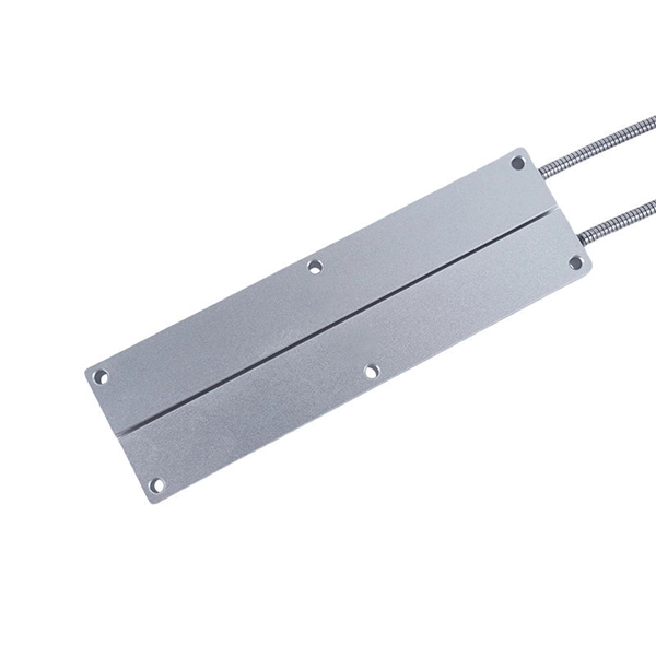
Step-by-step instructions on how to install fiber optic connectors like LC, SC, and ST. Includes tool recommendations, epoxy and polish method, and safety tips for installers and technicians. Even with sharing in efficiency, fiber connector installation is still an effort in which precision and safety form the central themes. A correct installation creates a low-loss, reliable connection essential for high-speed data transmission. While fiber optics enable speeds and distances copper can't match, the system's performance hinges. Next, we will introduce in detail the installation of several different types of fiber optic connectors. How To Connect Fiber Optic Cable To Connector? The connection methods for SC, FC, ST, and FT connectors with optical fibers are basically the same. Unlike foil strain gauges, fiber is often suitable for embedment. Sensuron's FOS offers hundreds to thousands of sensing points with a resolution of 1. 4 mm along a single sensing fiber. This video demonstrates the process of installing a fiber optic sensor to a substrate for measuring distributed mechanical strain. Fiber optic connectors are devices that join two fiber optic cables together, allowing the transmission of light signals with minimal loss. They come in various types, such as SC, LC, ST.
[PDF]
