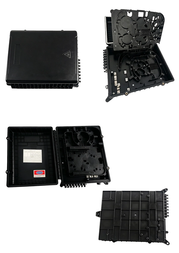
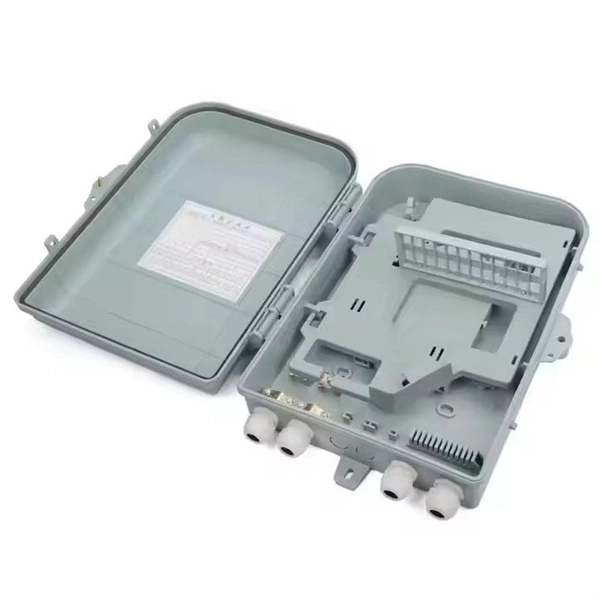
Please view our full RLH price list and contact us at info@fiberopticlink. com if you have any questions or special project needs. A Fiber Optic Patch Panel, also known as an Optical Distribution Frame (ODF) or fiber termination enclosure, is a centralized hardware unit designed to manage, protect, and organize fiber optic cable connections. In an era where data speeds and network reliability are non-negotiable, the patch. fiber optic patch panel, odf, optical distribution frame, fiber distribution panel, rack mount fiber patch panel, wall mount odf, fiber termination box, 1u fiber patch panel, 24 port fiber patch panel, 48 port fiber patch panel, outdoor fiber patch panel, fiber optic odf, sliding patch panel The. Q1: What is the difference between an ODF and a patch panel? An ODF is the entire frame or cabinet managing fiber connections, while a patch panel is a modular unit inside the ODF for cross-connecting fibers. Q2: How many fibers can an ODF handle? It depends on the ODF type; rack-mount units can. ODF is used in the terminal access link of FTTH system. It is a device that splices, distributes, and splits optical fibers and provides protection and management of optical fibers. Belden offers several Fiber Patching Systems. Full patching platforms include FX ECX for LAN environments, FX UHD for high-density fiber channels and the DCX System used primarily in data centers where high amounts of fiber connections and density are the key requirements, as in optical.
[PDF]
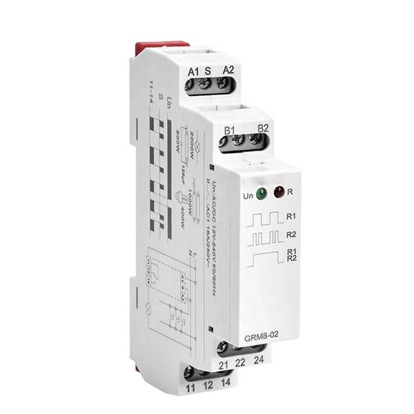
In this step-by-step tutorial, we'll cover: ✅ Tools you need ✅ Safety precautions ✅ Mounting the box ✅ Wiring tips ✅ Final checks Perfect for beginners, DIYers, and electricians who want a clear installation guide. more Learn how to properly install an electrical . Learn how to install a distribution box safely and correctly. Covers wiring, placement, standards, and expert tips for a compliant setup. A distribution box is the heart of any electrical system. It takes the incoming power and safely distributes it to different circuits throughout your building. It has three categories: residential, commercial and industrial electrical distribution boxes, all of which play important roles in their respective electrical. In modern electrical systems, cable distribution boxes (also known as electrical distribution boxes or distribution boxes) play a crucial role as the key hub for managing, distributing, and protecting circuits. Whether it is residential buildings, commercial facilities or industrial sites, the. The National Electrical Code has a few restrictions on where electrical panels may be located, as follows: NEC 110. 26 requires electrical equipment (including electrical panels) to be located to provide required working clearances about the equipment. You can find electric panels inside cabinets, behind refrigerators, or inside clothes closets in older homes. Current National Electrical Codes (NEC) allow none of these locations. Electrical panels.
[PDF]

Welcome to our step-by-step guide on installing cable trays! In this video, we'll explore the different types of cable trays available and provide detailed instructions for their installation. Whether you're an experienced electrician or a DIY enthusiast, this. Whether you're building a commercial setup or upgrading an industrial plant, proper cable tray installation ensures neat wiring, safe access, and easy maintenance. But before you lay the first tray or clamp down a single cable, you need a solid plan. This guide breaks down the process step by step. Installing a cable tray system requires careful planning to ensure it can support the weight of the cables and adheres to electrical safety codes. Here is a step-by-step guide on how to install a standard metal cable tray system (e., ladder or perforated type). more. The purpose of this article is to define the sequence and methodology for the installation of electrical cable trays, cable trunking, cable raceways and boxes, junction and pull boxes. The method gives details of how the work will be carried out and what health and safety issues and controls that. Cable tray systems are designed for easy installation and to accommodate power, communications, and signal cabling across a variety of applications. When installed and engineered properly, cable.
[PDF]
Supported by air within insulated pillars, the busbar collects incoming electricity and conducts it for distribution to outgoing feeders. They are typically made from solid or hollow conductive metals, such as copper, aluminum, or brass. In electric power distribution, a busbar (also bus bar) is a metallic strip or bar, typically housed inside switchgear, panel boards, and busway enclosures for local high current power distribution, transmission, or switching substations. Its primary role is to carry large current loads and connect multiple circuits together. Think. A bus bar offers a low electrically resistant path to incoming or outgoing currents. Find out more about them in this article. What is a bus bar? An electrical bus bar is a solid-state conductor made from copper and aluminum- present in the industry for over 150 years. It carries higher amount of currents in a limited space and to which all the incoming and outgoing feeders are connected in a substation.
[PDF]
This guide walks you through a safe, code-aware way to add a weather-ready receptacle near planting beds or a patio. If local rules differ, follow your jurisdiction's code and pull a permit when needed. Pick a spot that keeps the box out of splash zones and mower paths. Installing an outdoor GFCI receptacle in a garden takes planning, code-rated parts, and safe wiring in conduit or UF cable. Great for adding outlets, lighting, or appliances outside. more Need outdoor power? In this video, I'll show you how to install a weatherproof outdoor. Installing an outdoor electrical outlet can significantly enhance the functionality of your outdoor space, making it easier to power tools, lights, and appliances without fuss. This article details the process of installing them, which helps you comprehend distribution boxes. This comprehensive guide will equip you with the expert knowledge to safely install your outdoor electrical box, from understanding crucial wiring tips and essential GFCI protection to implementing industry best practices. Let's illuminate your outdoor projects, the right way. However, proper installation is essential for safety and local code compliance. The good news is that you don't need.
[PDF]
Just snap the dust cap over the electrical connector or port for which it's designed. This manual details the installation, operation and maintenance instructions for type JBDB Junction/Terminal Box (flameproof). This product is ATEX and IECEx certified to meet the requirements for hazardous location equipment. You don't need any special tools or equipment to install a dust cap. Once installed, the dust. As with most tasks, there are many ways to terminate motor leads and each one has a following who believe it is the best method. Here we will discuss some of these procedures and outline a few of the advantages and disadvantages of each. We will not consider the starting method or inter-nal. An electrical junction box is a protective housing designed to enclose and shield electrical wire connections or splices. For outdoor installations, the box must defend these sensitive splices against moisture, dust, temperature fluctuations, and physical impacts. Using a purpose-built.
[PDF]
This guide covers the critical steps, from selecting the right electrical cable tray and performing accurate cable fill calculations to managing a safe cable pull through and ensuring all bonding and grounding requirements are met. Article Summary: A compliant cable tray installation requires a thorough understanding of NEC Article 392, proper structural support, and precise installation techniques. But before you lay the first tray or clamp down a single cable, you need a solid plan. This guide breaks down the process step by step. Here is a step-by-step guide on how to install a standard metal cable tray system (e., ladder or perforated type). Before starting, ensure you have. NEMA VE2 addresses cable tray installation and provides information on maintenance and system modification. NEMA VE2 was developed by the NEMA Cable Tray Section, of which MP Husky is a charter member. Ladder Cable Trays Solid side rail protection and system strength with smooth radius fittings and a wide selection of materials and finishes. Maximum strength for long span applications. Welcome to our step-by-step guide on installing cable trays! In this video, we'll explore the different types of cable trays available and provide detailed instructions for their installation. Whether you're an experienced electrician or a DIY enthusiast, this video is perfect for you.
[PDF]
Step-by-step on-site guide: learn how to plan, mark, support, and install cable trays correctly, from shop drawing approval to final checks. Method Statement installation of Cable Trays and Ladders - Planning Engineer FZE. The Cable Tray system is installed in electrical rooms, plant rooms, and service. Whether you're building a commercial setup or upgrading an industrial plant, proper cable tray installation ensures neat wiring, safe access, and easy maintenance. But before you lay the first tray or clamp down a single cable, you need a solid plan. This guide breaks down the process step by step. In order to get it right, installers are supposed to adhere to a plan that ensures that wires are kept cool and the building is stable. The beginning of success is to review the Bill of Quantities (BOQ) so that. In this post, we will see together how to install cable tray on-site. Firstly, we need an approved shop drawing that shows the cable tray route, its dimensions, installation height, support system, the number of layers of these trays, and the type of systems they will serve. The key requirements for cable tray installation include: Incorrect installation can lead to overheating, cable damage, or system failure. This guide covers the critical steps, from selecting the right electrical cable tray and performing accurate cable fill.
[PDF]
Trending price is based on prices over last 90 days. Find many great new & used options and get the best deals for 3M 6366 Hot Melt Fiber Termination Kit 120v Tested at the best online prices at eBay! Free shipping for many products!. Trending price is based on prices over last 90 days. The result is a quick mount. The 8602-S Hot Melt LC is a singlemode. Check each product page for other buying options. Need help?. FS fiber optic pigtails offer a fast way to make fiber optic communication devices in the field by fiber splicing, fully manufactured and tested by industrial standards. 3M Model 6312 Hot Melt Fiber Optic Connector Termination Kit WITH CASE & EXTRAS! item 3 3M Model 6312 Hot Melt Fiber Optic Connector Termination Kit WITH CASE & EXTRAS! Wiha Tools 91872 Master Electrician's Insulated Tool Kit 59 Pc. Find many. TXM's Quick Assembly Hot Melt connectors provide a quick and easy termination of fibers in the field. Our field connectors are universal and applicable for 0. 9mm Tight Buffer Fiber, 2. These field connectors allow the installer to terminate fiber in minutes out in the. Log in or register to view your price, purchase history, and more! The Hot Melt Termination Kit 6366 contains all materials needed to install SC, ST and FC Hot Melt Connectors, both multimode and single-mode. Kit comes with a 120V oven. 3M Hot Melt Termination Kits 6366 (120V oven) and 6362 (230V.
[PDF]
In this step-by-step tutorial, we'll cover: ✅ Tools you need ✅ Safety precautions ✅ Mounting the box ✅ Wiring tips ✅ Final checks Perfect for beginners, DIYers, and electricians who want a clear installation guide. more Learn how to properly install an electrical. Learn how to install a distribution box safely and correctly. Covers wiring, placement, standards, and expert tips for a compliant setup. A distribution box is the heart of any electrical system. It takes the incoming power and safely distributes it to different circuits throughout your building. Before starting the installation, finding a proper place for putting the distribution box is crucial, because it largely decides the safety and convenience of maintenance. Let's see what factors need to be taken care of when choosing the installation place. Whether it is residential buildings, commercial facilities or industrial sites, the. Dear Mr. Electrician: How do I install an electrical box in a narrow space? NOTE: Text links below go to applicable products on Amazon. As an Amazon Associate, I earn from qualifying purchases. Using my links helps to keep this website FREE. Warm reminder: Do not disassemble or modify without experience and professionals. Select location Before.
[PDF]

The first thing you should do is locate the fiber optic cable that comes from the service provider. Once inserted, make sure it is securely. However, setting up a fiber optic connection to your router can seem daunting if you're unfamiliar with the process. Why Use Fiber Optic Internet? Before diving into the setup, let's quickly. Ensure your fiber optic router has an available WAN (Wide Area Network) or Ethernet port for the fiber optic modem. It's thin, flexible, and usually comes with connectors on both ends. Power Cables: Get power cables for both the. The fiber optic cable does not plug directly into a standard home router because the signal type must be translated. The fiber line terminates at the Optical Network Terminal (ONT), which is typically supplied and installed by the internet service provider. This specialized equipment serves as the. The process to connect fiber optic cable to router requires careful attention to detail, but I'll walk you through every critical step with the precision and clarity you deserve. Here's a step-by-step guide to help you through it. Understand the Basics Before diving in, familiarize yourself with the components involved:. Follow along as we take you through the step-by-step process of installing fiber internet! From preparing the site to connecting the final cables, we'll show you what goes into bringing high-speed internet to your doorstep. Whether you're a tech enthusiast or just curious about how it all w.
[PDF]
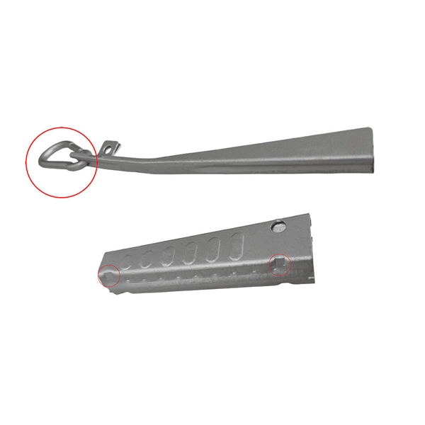
Attach a ground wire from one of the threaded studs (A) at the bottom of the housing, to the mounting plate (B). The ground resistance between all system parts shall be <. The protective grounding system, which includes conductor grounds and worker bonding, must be engineered to protect workers from hazardous voltages that can be created by line reenergizing, lightning, or induced oltage. If more than one crew is working independently on the same deenergized line or. Power from factory ground must be installed by a qualified electrician. Each DISTRIBUTION BOX and controller must be grounded. On the US market, a 5. 26 mm 2 (10 AWG) ground wire must be used, and in all other markets a 6 mm 2 must be used. The neutral conductor is typically the grounded conductor connected to the system's neutral point, carrying current under normal operation. Grounding electrode conductors must be connected at. The correct connection method of Distribution box grounding wire mainly includes the following steps: 1. Whether you're a seasoned pro or just starting out, this comprehensive guide will give you practical. This technical article covers protective grounding requirements for steel tower and wood pole supported transmission and distribution lines, and insulated power cables. Protective grounds must be installed so all phases of lines or cable are visibly and effectively bonded together in a multi-phase.
[PDF]

Professional Cable Tray Elbow Making | Metal Fabrication Tutorial Learn how to make cable tray elbows professionally with step-by-step guidance. This video shows metal fabrication techniques, DIY cable tray projects, and tips for perfect bends and joints. Whether you are a DIY enthusiast. The method for producing bridge bend elbows is as follows: Take a 90-degree cable tray bend elbow as an example, and apply the same principles for 45-degree bends accordingly. The length of the bottom side (bottom diagonal) after bending the cable tray should be equal to the width of the cable. This manual is designed to guide workers through the detailed production process of ladder cable trays, including the manufacture of horizontal elbows, tees, crosses, reducing bends, and vertical bends, with emphasis on precision, safety, and quality control. What's Involved in Producing Ladder. The bends, tees, crosses, risers and reducers of wire mesh cable tray can be easily and quickly made live at the project by using a bolt cutter. Since the jaws of the bolt cutter drags a layer of zinc across the cut end and forms a protective layer. When a wire cable tray is cut, the fact that a. How to bend 22. 5 DEGREE OF CABLE TRAY 3 LA. How to bend 90 degree of cable tray 3 line with the same distance :// • HOW TO BEND 90 DEGREE OF CABLE TRAY 3 LINE. Enjoy the videos and music you love, upload original content, and share it all with friends, family, and the world on YouTube.
[PDF]

This helps keep fiber optic cables safe from harm and signal problems when you put them in. Use the right lubricant. Follow the rules for tension and bend radius. Try new methods like air blowing. Use smart. Fiber optic cable is surprisingly strong, durable and pliable; however, several best practices should be followed to ensure a successful cable installation. This article explores recommendations for pulling and installing fiber optic cable. This makes sure the cable pull is smooth and safe. Use smart monitoring devices. The Future Ready Solutions Tools & Test. A duct is available from point A to point B, a pull tape is blown in, a fiber optic cable is attached to it and the cable is pulled through the duct. Sounds simple, doesn't it. Recent observations and conversations with more than a few people in the fiber optic business have indicated. Route plan to ensure the duct run maintains the minimum bend diameter of the cable. For more information and all recommendations for installation, refer to Corning Optical Communications Standard Recommended Procedure SRP 005-011, "Duct Installation of Fiber Optic Cable". more Route plan to ensure.
[PDF]

Learn how to splice fiber optic cable using fusion splicing with this complete step-by-step guide. Includes tools, best practices, loss standards (ITU-T G. 652), cost analysis, and FAQs for network engineers and installers. 5,398 fiber splicing stock photos, vectors, and illustrations are available royalty-free for download. Template technician Fiberoptic Fusion Splicing. Worker connecting for Cable Internet signal and Wire connection with Fiber Optic Fusion Splicing machine,fiber optic cable splice machine in work. Splicing fiber optic cable is an extremely important phase for making dependable, high-speed communication infrastructures. Regardless of the type of fiber network you're deploying, be it for telecom, enterprise data centers, or smart city infrastructure, fusion splicing provides the benefits of. In this guide, we cover the basics of fiber optic splicing, how to perform splicing using two different methods, and finally some best practices to perform good fiber splicing. Ensure Your Splicing Tools are Clean – #2. For network managers and technicians, a poor splice can lead to significant signal degradation, network downtime, and costly troubleshooting. At Turn-Key. 🔧 Watch a real-time fiber optic splicing demo in action! In this step-by-step tutorial, learn how to splice fiber optic cables like a pro — perfect for telecom technicians, network engineers, and field techs.
[PDF]