
Use a fiber optic stripper to remove the protective jacket from the end of the fiber. Be careful not to nick or damage the fiber itself. This is an outdoor rated fiber that is very. Fiber patch cables can be used with many network devices, such as optical transceiver modules, fiber adapter panels, fiber cassettes, media converters, and other products having fiber optic interfaces. The actual steps may vary depending on the cable and/or connectors. Fiber optic cables are typically damaged in one of two ways: A premade fiber optic cable suffers connector damage when too. However, if the cap is too tight to pull using your finger, you can use a pair of soft-tipped tweezers to remove it gently. Step 2: Using your fingers or the tweezers, grasp the cap's edges. To strip and clean outdoor FO cable, you have to start with the outer jacket. Step 1: Mark the armor (if the cable has armor) with the tip of your knife to note a length sufficient to expose the cable's ripcord, being careful not to go through the armor and cut the ripcords. Step 2: Cut and remove. Gather the required tools before attempting to remove a fiber optic LC connector. A dust cap, a fiber optic connector cleaner, and a lint-free cloth are required. Examine the Connector You.
[PDF]
The LS-SM3101-20C SFP transceivers are high performance, cost effective modules supporting data rate of 125Mbps/155Mbps and 20km transmission distance with SMF. The transceiver consists of three sections: a Cooled EML laser transmitter, a APD photodiode integrated with a trans-impedance preamplifier (TIA). The AFCT-5745NPZ/UPZ Lead-free Singlemode Optical Transceivers have been qualified in accordance to the requirement of Telcordia Document GR-468-CORE under the supervision of Avago Technologies Quality & Reliabil-ity Department. This report summarizes the qualification tests over a range of. Copyright © 2022 GOC-UZ. See our terms of use and privacy policy. Volza's Solution gives you 100x return in Six Months! Use strategic filters to explore Optical transceiver module Import data like a seasoned analyst, uncovering hidden opportunities in the Optical transceiver module import business. Our database includes 321 Import shipments, involving 63 Buyers. Up to now, MEISU has developed various high-temperature resistant optical devices not only with regular SM fiber, but also with PM fiber array by applying special high-temperature coating to the normal PM fiber, providing muiltiple choices for silicon photonic (SiPh) solder reflowable assembly at.
[PDF]

View price, stock and buy direct from Transceiver USA. Customize your 1/10/25/100/200/400G transceiver from data rate, connector type, compatilibity to form factor. With well-equipped lab, all FS custom optical transceivers are produced with high-quality components, offer a five-year warranty and fast shipping. Purchase from nearby warehouses. This article compares typical cost ranges across speeds and transceiver types, explains why prices vary, and gives practical guidance for choosing the right optics for a given. This post offers quick access to the SFP module price list by researching top vendors. SFP modules have been in large demand in data centers with the continuous development of optical communication. Also, the SFP module type upgrades rapidly. It has been experienced from the initial version of 1G. Optical Transceiver Modules/SFP, also called fiber optic transceiver or optical transceiver, is a typically hot-pluggable device used in high-bandwidth data communications applications. While optical transceiver development has gotten simpler over the years, it does involve full engineering development to design, validate, and qualify. Generally, the two main milestones in this phase are. An Optical Transceiver is a critical optoelectronic component that facilitates seamless electro-optical (E-O) and photo-electric (O-E) conversion within fiber-optic networks.
[PDF]
This guide covers the critical steps, from selecting the right electrical cable tray and performing accurate cable fill calculations to managing a safe cable pull through and ensuring all bonding and grounding requirements are met. Article Summary: A compliant cable tray installation requires a thorough understanding of NEC Article 392, proper structural support, and precise installation techniques. But before you lay the first tray or clamp down a single cable, you need a solid plan. This guide breaks down the process step by step. Here is a step-by-step guide on how to install a standard metal cable tray system (e., ladder or perforated type). Before starting, ensure you have. NEMA VE2 addresses cable tray installation and provides information on maintenance and system modification. NEMA VE2 was developed by the NEMA Cable Tray Section, of which MP Husky is a charter member. Ladder Cable Trays Solid side rail protection and system strength with smooth radius fittings and a wide selection of materials and finishes. Maximum strength for long span applications. Welcome to our step-by-step guide on installing cable trays! In this video, we'll explore the different types of cable trays available and provide detailed instructions for their installation. Whether you're an experienced electrician or a DIY enthusiast, this video is perfect for you.
[PDF]
Typical rates range from $0. 00 per ft depending on terrain, access, and required precision for termination. Basic — 1,000 ft single-mode run indoors with minimal termination: Cable $0. 00/ft, Permits $150, Accessories $100. Total ≈ $2,650–$3,100. EU - Optical Fiber Cables and Bundles - Market Analysis, Forecast, Size, Trends and Insights. Update: COVID-19 Impact This report provides an in-depth analysis of the optical fiber. CRU provides comprehensive, accurate and up-to-date price assessments and research reports for bare optical fibre across various key regional markets, combined with insights into the factors and events affecting markets. The total consumption indicated a noticeable increase from 2012 to 2025: its value increased at an average annual rate of X% over the last twelve-year period. The trend pattern. Buyers typically pay for fiber optic cable by length, fiber type, and installation complexity. Main cost drivers include cable grade (indoor vs outdoor, armoured), distance, and labor for trenching, splicing, and termination. Commercial building installations with 100-200 network drops generally range from $15,000 to $30,000. Single-mode fiber costs less per foot than multimode fiber, but it requires more. The unit cost of fiber optic cables can vary from $0. Here's a general pricing reference: Cable TypePrice Range (USD/meter)Simplex / Duplex Indoor Cable$0. 50Multimode (OM1/OM2/OM3)$0.
[PDF]

Average Optical Power: How bright the light is (measured in dBm). Too dim? Your signal gets lost in the fiber. Extinction Ratio: The difference between “on” (1) and “off” (0) light power. A higher ratio = cleaner signals. Transmitter Side: An electrical signal hits a laser diode (LD) or LED, which spits out light. Receiver Side: Light enters a photodetector (like a tiny solar cell), which turns it back into electricity. A built-in amplifier boosts the signal for your. The average transmitted optical power refers to the optical power output by the light source at the transmitting end of the optical module under normal working conditions, which can be understood as the intensity of light. In communication, we usually use dBm to represent optical power. However, in practical use, we adopt the average Tx power. The transmission power is related to the. This article provides an in-depth analysis of two key performance indicators of optical modules: transmitter power and receiver sensitivity. Transmitter power characterizes the average optical power output from the laser under rated conditions, while receiver sensitivity indicates the minimum. An optical module is a connecting module that serves as an optical-electrical conversion device. At the receiver end, the optical signals are reconverted into electrical.
[PDF]

This article will provide an in-depth analysis of outdoor cable types, key selection criteria, core installation steps, critical precautions, as well as subsequent testing and maintenance guidelines, helping you build a robust and durable outdoor optical communication link. Therefore, understanding the characteristics of outdoor fiber optic cables and mastering proper installation methods is crucial. Plan your outdoor fiber installation carefully by surveying the site, choosing the right cable type, and following FOA and OSP standards to ensure reliability. In this video, we'll walk you through the process of establishing a robust outdoor fiber connectivity solution. Follow our guide and establish a r. more Welcome to. Running a cable through an exterior wall can be a daunting task for many homeowners, but with the right tools and techniques, it can be done efficiently and safely. With the increasing demand for high-speed internet and reliable networking, it's essential to know how to properly install CAT 6 cables outdoors. In this article, we'll take you.
[PDF]

This quick-reference guide focuses on what to measure, how to interpret results, and what to do when findings indicate marginal performance. Whether you're a network engineer validating new inventory or an integrator preparing for deployment, knowing how to test optical transceiver modules can save time, reduce failures, and ensure SLA compliance. Unchecked optical modules can cause: Testing ensures compliance with IEEE 802. 3 and MSA. This article provides a comprehensive guide on measuring key performance indicators to evaluate the functionality of optical modules, with a specific focus on the sfp28 transceivers. A comprehensive understanding of the working principle of an optical module is essential for determining the. Evaluating the performance of optical modules is a practical discipline: you must verify optical power and signal quality, confirm electrical/optical compliance, validate link-level behavior under real traffic, and document results in a way that supports reliability engineering. This. The optical module serves as a crucial component in optical fiber communication systems, operating at the physical layer, which is the lowest layer in the OSI model. Its primary function is to achieve optoelectronic conversion by converting electrical signals into optical signals and vice versa.
[PDF]

This guide provides a complete framework for understanding, identifying, and planning MPO connector gender in data center environments. Visually, male and female MPO connectors are easy to distinguish: male connectors feature two alignment pins (PIN pins), while female connectors have corresponding holes instead of pins. An MPO connection is made between a male and female connector to make sure that there is proper alignment. Interfaces on active MPO equipment, such as transceivers are usually male, so any MPO trunk cable. In modern data centers and high-density fiber optic networks, MPO (Multi-Fiber Push-On) connectors have become an essential solution for achieving fast, reliable, and scalable connectivity. You will discover the physical distinctions between male and female connectors and how to develop a gender strategy for your infrastructure, which gender connects. Whether you're supporting parallel optics like 100G SR4 or densifying an optical distribution frame (ODF), MPO is now a cornerstone of network design. This article explains: And a practical checklist to design MPO systems that scale cleanly. If you only remember one thing: MPO is a multi-fiber. In MPO and MTP fiber connector systems, Male vs Female and Pin vs No-Pin describe the same core engineering attribute: the presence or absence of alignment pins on the MT ferrule. Unlike single-fiber connectors such as LC or SC, this distinction is not optional terminology but a mandatory.
[PDF]

The core measurement procedure follows five steps: Turn on the meter and let it warm up. Most meters need a brief stabilization period before readings are reliable. Check your model's manual, but a minute or two is typical. Set the wavelength to match your light source. Fiber loss is the difference between the power when light is coupled from the transmitting end to the fiber and the power when the light reaches the receiving end. Generally speaking, when measuring the. An optical power meter measures the strength of light traveling through a fiber optic cable, giving you a reading in dBm (decibels relative to one milliwatt). The basic process is straightforward: turn the meter on, set it to the correct wavelength, clean your connectors, plug in, and read the. A power meter and light source are essential test tools that work in tandem to measure fiber optic cable loss and evaluate the quality of optical links. They provide the data necessary to quantify signal loss and pinpoint issues that could impact network performance. Here's how they work: A power. You measure optical power in dBm or insertion loss in dB. Verify light travels from transmitter to receiver. We'll give you the basic information you need and provide some printable references.
[PDF]

Not all splitters are created equal. Here are the main types you'll encounter: The "1×N" notation indicates one input fiber and N output fibers. A 1×2 splitter divides the signal into two outputs, while a 1×8 splitter divides it into eight. The more splits, the. By dividing a single optical signal from a central Optical Line Terminal (OLT) into multiple outputs for Optical Network Terminals (ONTs) at users' homes, splitters eliminate the need for dedicated fibers to each residence—slashing infrastructure costs while scaling network reach. This guide. A fiber-optic splitter, also known as a beam splitter, is based on a quartz substrate of an integrated waveguide optical power distribution device, similar to a coaxial cable transmission system. The optical network system uses an optical signal coupled to the branch distribution. The fiber optic. Optical couplers can split or join signals in fibers. You can connect many users to one port with 1:n or 2:n splitters. These devices work both ways, which helps strong network communication. In a Passive Optical Network (PON), a single optical fiber carries massive amounts of data using light. They are named by the number of inputs and outputs, so a splitter with one input and 2 outputs is a 1X2, and a PON splitter with one input and 32 outputs is a 1X32.
[PDF]
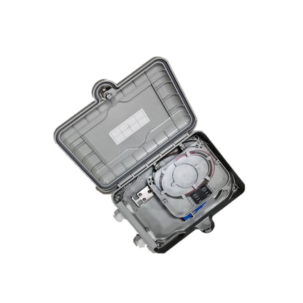
Learn how to install a fiber optic termination box step-by-step for FTTH projects. Covers mounting, splicing, routing, labeling, and testing for indoor/outdoor use. Installing a fiber optic termination box is one of those jobs that looks simple on paper, but it's easy to do poorly in the field. If you do not have relevant experience and skills, it is recommended to ask a professional to install it. Preparations: Before installation. How to install the FTTH terminal box? - YouTube This kind of box are used in the end termination or residential building sand villas, to fix and splice with pigtails, can be installed on the wall. When it comes to ONT installation, you've got two main options: Indoor ONTs are installed inside your home, typically in a utility room, basement or another centralized spot. Both options have their advantages, and the choice. A fiber termination box is the standard instrument used in fiber optic networks to connect, secure, and protect optical fibers at the terminating point. To install a junction box correctly, choose a box that matches the wiring method and environment, mount it securely, bring cables in.
[PDF]

This guide provides a clear, step-by-step explanation of how to install an SFP module correctly, based on real-world deployment practices. The fastest way to do so is by unplugging the power plug from the power outlet. This is a Class A product. In a domestic environment, this product might cause radio interference in which case the user might be required to take adequate measures Electric shock hazard. This equipment is to be. This Quick Guide covers the model: CCR2004-16G-2S+PC. You can find the product model name on the case label (ID). Or scan the QR code with your mobile phone. lv/um The most important. The Installation of the equipment must comply with local and national electrical codes. Please read the mounting instructions carefully before beginning installation. Failure to use the correct hardware or to follow the correct procedures. The CCR2004 is a high-performance multicore router with twelve 10G SFP+ ports and two 25G SFP28 ports. Before you work on any equipment, be aware of the hazards involved with electrical circuitry, and be familiar with standard practices for preventing accidents. It covers critical preparation checks, proper insertion techniques, hot-swap and safety considerations, common installation mistakes, and practical. The Cisco 8000 series routers support both ZR and ZR+ modules. The Cisco 8200 Series uses a single Cisco Silicon One ASIC to deliver full routing functionality. These fixed port, high-density routers provide 10.
[PDF]

Product Range: PLC splitters, FBT splitters, fiber optic adapters, patch cords Price Range: $5 to $150 depending on splitter ratio and specs Overview: TTI Fiber is a global supplier known for quality optical components. FBT (Fused Biconical Taper) Fiber Optic Splitters. These devices splits the fiber optic signal from a single Input to two Outputs. Available in 50/50, 30/70, and 90/10 spit ratios. A fiber optic splitter is different from WDM. WDM can divide the. FBT (Fused Biconic Taper) Coupler Splitter is a commonly used fiber optic coupler and splitter for distributing optical signals to multiple output channels. FBT splitters are reliable and cost-effective, typically used for smaller split ratios like 1x2 or 1x4. The physical packaging or form factor of a splitter is crucial. FBT Coupler Splitters is widely accepted and used in passive optical networks, especially for instances where the split configuration is smaller (1×2, 1×4, etc. FBT is the traditional technology in which two fibers are placed closely together, typically twisted around each other and fused. FBT Fiber Splitter, also known as a fiber optical coupler, separates fiber optic light into many portions using a predetermined ratio. Unlike PLC splitters, FBT splitters employ distinct splitting methods and may be constructed using singlemode, multimode 62. 5, or multimode 50 fibers.
[PDF]

One of the core advantages of MPO patch cords is their high-density integration. Traditional patch cords have only 1-2 cores per cord, while MPO patch cords can integrate 12-48 cores, enabling multi-port connections with a single cord. Fiber cores are the heart of fiber optic cables, transmitting light signals that carry data. Made from either high-quality glass or plastic, the core plays a critical role in determining the cable's performance. The total number of cores for a 1pc fiber patch cable is calculated as the number of. Multi-core patch cords are fiber assemblies containing multiple fibers within a single cable jacket, typically available in 4, 6, 12, and 24-fiber configurations. The outer sheath is clearly marked with core count indicators. MTP/MPO cables are a class of high-density multi-core fiber optic connectivity solutions widely used in data centers and telecom networks, which are designed to achieve fast connection of multi-core fiber optics through a single interface. In the context of accelerating digitalization, the rational. The 16-core MPO patch cord, a high-density optical fiber connector, has become an ideal choice for 400G networks and beyond due to its superior optical performance, flexible compatibility, and efficient cabling capabilities. This report analyzes the key technical parameters, primary application.
[PDF]