Learn how to connect your ONT, configure your router, and optimize Wi-Fi for fast, stable fiber internet at home or office. To set up your router for fiber internet quickly, connect the router to your fiber modem, access the router's settings via a web browser, and input the provided ISP credentials. Make sure to update the firmware, configure Wi-Fi security, and customize your network name for optimal performance. With. However, setting up a fiber optic connection to your router can seem daunting if you're unfamiliar with the process. In this guide, we'll walk you through how to connect a fiber optic cable to a router safely and efficiently. Why Use Fiber Optic Internet? Before diving into the setup, let's quickly. Setting up a fiber internet connection requires understanding key hardware components and following a specific connection sequence to establish your home network.
[PDF]
Inside the distribution box, you'll also find switches and indicators. The switches are used to control the circuits—turning them on or off as needed. A distribution box, also known as a distribution board, electrical panel, or breaker box, is an enclosure that houses electrical components responsible for distributing electricity throughout a building. It receives power from the main electrical supply and divides it into separate circuits, each. Messy distribution boxes are dangerous and very hard to fix. This guide shows you how to organize circuit breaker wiring properly. You will learn to build a safe, efficient, and professional electrical system today. Indicators, like LED lights, show the. A distribution box uses MCBs, RCDs, and busbars to protect circuits, prevent shocks, and ensure safe power distribution in homes and buildings. It acts as the central point where electricity distribution is managed inside a building. These diagrams provide a visual representation of how the electrical circuits are connected, allowing electricians and homeowners to troubleshoot issues.
[PDF]
An aggregation layer usually comprises a few blocks of two switches in MCLAG. By design, it therefore provides resiliency because it will always be deployed in pairs of switches and comes with a recommendation to deploy only dual hot swappable power supplies and redundant fans in each switch to. IEEE 802. 3ad link aggregation enables you to group Ethernet interfaces to form a single link layer interface, also known as a link aggregation group (LAG) or bundle. The LAG balances. Switch-to-Switch Aggregation: This is useful in scenarios where you need to interconnect multiple switches to increase the bandwidth available between them and ensure network redundancy. It helps in managing higher traffic loads between switches. Switch-to-Client Aggregation: This is beneficial. An Aggregation or "Top-of-Rack" switch is designed to connect everything in a rack at high speeds, then have an even bigger pipe out to the rest of the network. The Pro Aggregation does this with it's SFP28 25Gbps ports. While there are many approaches, this article. Would I have any issues if I linked a Ubiquiti aggregation switch to another? We have some fiber runs in our building, but there isn't enough runs to supply all my switch locations and a couple of the runs are too long for 10gig. So, what I want to do is install an aggregate switch at the source.
[PDF]
Learn more!. Learn more!. Check our Latest Networking Switches with best features and cost efficient, Heavy on Features not on Pocket Purpose-engineered solutions for the three pillars of India's network infrastructure ecosystem. Deploy advanced switching solutions across access and aggregation layers. Built for. The product has completed the End of Life (EOL) process effective on January 1, 2026. For more details, please refer to the EOL Notice. The Edgecore AGR100 router meets the high-performance, availability, and network-scaling requirements of cloud data centers and carrier access providers. 8 Tbps high-density 100G/25G Layer 3 Etherlighting™ aggregation switch with MC-LAG support for high availability system design. Requires a 4-post rack, or a center-mount bracket or cantilever shelf on 2-post racks for optimal support. Contact your EET Sales for the needed Ubiquiti Registration. Enterprise Campus Aggregation. Designed to combine compressed and uncompressed video / audio streams as well as TCP traffic over IP, the MDX series is ideal. Individually Configure Ports for Optimum Flexibility The AA100G32AC is a purpose built network aggregator, designed for use in top-of-rack applications or at the network edge. The system can be used to optimize port utilization of existing infrastructure or as a stand alone device in L2-L4.
[PDF]
In conventional network construction, we divide the switches into a hierarchical structure according to the number of connected network devices. Typically, we have three structural levels: access, aggregation, and core. An aggregation switch is a network device that consolidates traffic from multiple access switches, wireless access points, or other edge devices and forwards it to core switches or routers. By bundling multiple network connections into a single high-bandwidth link, aggregation switches help. Whether in enterprise networks, data centers, or campus environments, aggregation switches act as a bridge between access switches and core switches. It is essential for larger networks requiring efficient data flow. You may also. Due to all traffic in a system is transmitted to the core switch, it is required to have high reliability, high efficiency, manageability, and low latency. Generally, it adopts the managed switches in the core layer. The core layer is an integral part in networking, but it is not requested in all. Switch aggregation, also known as link aggregation or trunking, is a method used in computer networking to combine (aggregate) multiple network connections in parallel. This arrangement increases throughput beyond what a single relationship could sustain, offers redundancy in case one of the links.
[PDF]

This is the most fundamental ring topology, formed by connecting three or more switches in a closed loop using fiber optic cables. Data can flow in either direction, allowing the network to recover quickly if a link fails. If you have multiple Ethernet switches that need to be connected over long distances, fiber is obviously a preferred choice. Moreover, when it comes to bandwidth, no currently available technology is better than single-mode fiber. It can provide significantly higher bandwidth and carry more data. A single 6 strand fiber can only connect 3 switches back to the core. How many switches do you plan to connect? A star is great for a limited number of switches. I have maybe 20 coming back to my cores. Rings are generally not done anymore, but I think that is for bandwidth as much as anything else. The mainline of the fiber optic LAN directly connects to the switch, then to the router. The connection between two or more Ethernet switches in a certain way (Uplink port, etc. ) is called the cascade. All switches have two fiber ports. Is the best way to have fiber backbone switch and connect fiber channel from every switch to the backbone? Or connect switch 1 to switch 2 to switch 3 to. switch 12 to switch 1 again? Thanks! Let's get some. I need to connect 4 Floor Building with 4 Cisco 2960 - 48 ports switch each other and it needs to be through a fiber. This design ensures data can travel in both directions.
[PDF]

When you connect two 1000BASE-T switches with SFP ports to achieve Gigabit Ethernet, there are two methods: through standard Ethernet cable plugged into the built-in Ethernet ports of each switch, or use the SFP ports with a copper SFP module. 🎥 In this video, I show you how to connect two different branded switches using SFP modules and fiber optic cables. Whether you're using Cisco, Planet, TP-Link, D-Link, Ubiquiti, or any other brand — the key is understanding SFP compatibility. Before moving ahead, let us discuss some basics about standard Ethernet cables and 1000BASE-T (IEEE 802. Network topology refers to the way in which the links and nodes of a network are arranged in relation to each other. What Is a 10Gb SFP Module? A 10Gb SFP (Small Form-factor Pluggable) module is a compact, hot-swappable transceiver used to establish high-speed fiber. Did you swap one of the fiber connectors at one of the endpoints? Meaning, take off the housing of the fiber connector, and swap a and b. You'll find SFP / SFP+ specs on the datasheets for the switches. They're free to view and download from Cisco. Cisco also publish a GBIC /. Most modern fiber-enabled network switches require an SFP transceiver module featuring a duplex (two strand) multimode OM3 or duplex single mode OS2 connection with LC connectors. Direct attach cables with pre-terminated SFP connections may also be used. Download the Application PDF SFP transceiver.
[PDF]
A network switch (also called switching hub, bridging hub, Ethernet switch, and—by the —MAC bridge ) is that connects devices on a by using to receive and forward data to the destination device. A network switch is a multiport that uses to forward data at the (layer 2) of the. Some switches can also forward dat.
[PDF]

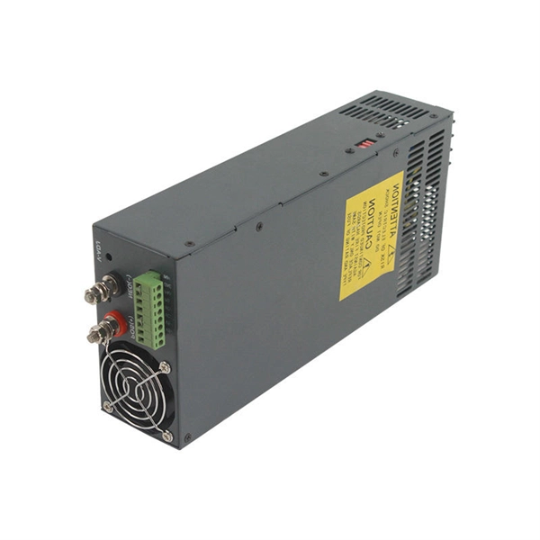
In today's video, we'll be unboxing the 9-Port Power Supply Box and demonstrating how to connect the cables to provide power to CCTV cameras. A CCTV power supply box sends power to all your cameras from one place. It helps keep things neat and makes your system easier to manage. In this guide, you'll learn how to install it step by step, choose the right type, avoid common problems, and keep your system running safely. Power supply boxes for CCTV are typically used in multi-camera installations instead of using single power adapters for each camera. The process is almost exactly the same if you. Installers of surveillance systems may simply control the power to various CCTV cameras using a CCTV power supply box, also known as a power distribution box (usually at the location of the DVR). This enables a cleaner camera installation. Surge protection can be accomplished in two ways. The power supply box is specifically used to transfer power requirements for all cameras plugged in on the system, to work. Security cameras use RG59U coax siamese wire or CAT5e networking cable to transmit video. Whether you are installing a power box for a new or existing camera system, it is important to understand how to connect cameras to a CCTV Power Supply Box. DC current is polarized meaning it has two leads, a.
[PDF]

Download a comprehensive set of Cable Tray Installation CAD Blocks in DWG format, ideal for electrical engineers, MEP designers, and industrial layout planners. Electrical cable tray layout is a ready-to-use CAD block perfect for building services, industrial setups, and electrical projects. This cable tray CAD block is compatible with AutoCAD and other DWG-supported software, allowing precise placement and easy integration into your designs. Save time and. Discover all CAD files of the "Cable trays" category from Supplier-Certified Catalogs ✅ SOLIDWORKS, Inventor, Creo, CATIA, Solid Edge, autoCAD, Revit and many more CAD software but also as STEP, STL, IGES, STL, DWG, DXF and more neutral CAD formats. This collection includes installation details for ladder trays, perforated trays, solid-bottom trays, and wire mesh trays, along with. Tray installation details for the location of a project's electrical wiring; in addition to blocks with different angles that allow the wiring circulation to be identified. Download this FREE 2D CAD drawing of CABLE TRAYS including various widths. This autocad drawing can be used in your mechanical design CAD drawings. dwg format) Our CAD drawings are purged to keep the files. Already Subscribed? Download free cable trays in DWG or CAD block format. Cable tray details.
[PDF]

In this guide, I'll walk you through everything you need to know about choosing the right cable trays for your cables. Whether you're dealing with power cables, control cables, or communication cables, I'll break it down step by step. A 50 mm cable tray is used to organize and protect cable routes in industrial, commercial, and infrastructure facilities. This compact solution is suitable for power distribution lines, low-current systems, and engineering communications. Mirankul Group manufactures cable trays in Uzbekistan. Accessories for cable systems include a variety of different components necessary for the proper functioning of cable routes. They provide a structured and secure pathway for cables, ensuring organized installation and easy maintenance. Cable Trays are important for ensuring the protection of the wiring system and supporting insulated electric cables used for distribution and communication. Brilltech Engineers Pvt. Understand Your Cable Tray Requirements Before selecting a cable tray, consider the following key factors:. Selecting cable trays can feel overwhelming, especially with so many options available. But don't worry—I've got you covered.
[PDF]

The typical cost of 1U space in a 45U server cabinet is $55. Therefore: Average cable management cost is . Basic cable management systems (cable trays, ties): $200 to $1,000 per rack. Power and Cooling Infrastructure Power Distribution Units (PDUs): $200 to $1,500 per unit, depending on capacity. 73/U The. Durable & Easy to Install: Made from sturdy plastic for long-term use in IT environments. Installs easily on standard rack rails using the included M6 screws-no special tools required Each item has a unique code that we verify before shipping. com Return Policy: Amazon. com. Sysracks offers a wide array of data closet cable management products for different devices: Horizontal managers: Our 1U wire managers are designed to suit any 19” cabinet. This allows structured routing of twisted-pair wires and patch cords and ensures the correct cord radius to prevent twisting. Shop top-quality rack cable managers for efficient data center wiring. Get a horizontal/vertical cable manager to safely organize and protect your cables. Our 1U and 2U cable managers reduce slack, improve airflow, and create clean, serviceable rack layouts designed for scalability.
[PDF]

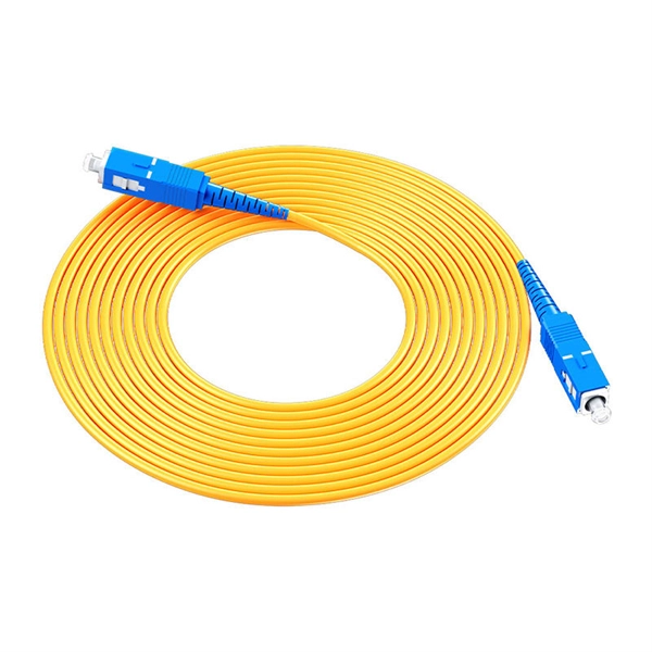
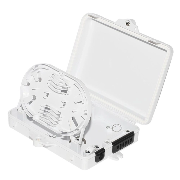
The first thing you should do is locate the fiber optic cable that comes from the service provider. Once inserted, make sure it is securely. However, setting up a fiber optic connection to your router can seem daunting if you're unfamiliar with the process. Why Use Fiber Optic Internet? Before diving into the setup, let's quickly. Ensure your fiber optic router has an available WAN (Wide Area Network) or Ethernet port for the fiber optic modem. It's thin, flexible, and usually comes with connectors on both ends. Power Cables: Get power cables for both the. The fiber optic cable does not plug directly into a standard home router because the signal type must be translated. The fiber line terminates at the Optical Network Terminal (ONT), which is typically supplied and installed by the internet service provider. This specialized equipment serves as the. The process to connect fiber optic cable to router requires careful attention to detail, but I'll walk you through every critical step with the precision and clarity you deserve. Here's a step-by-step guide to help you through it. Understand the Basics Before diving in, familiarize yourself with the components involved:. Follow along as we take you through the step-by-step process of installing fiber internet! From preparing the site to connecting the final cables, we'll show you what goes into bringing high-speed internet to your doorstep. Whether you're a tech enthusiast or just curious about how it all w.
[PDF]

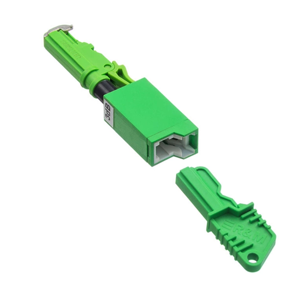
As fiber optic cables are generally only produced in lengths up to around 5 km, so when lengthier connections are needed, splicing two cables together becomes necessary. So in essence, fiber optic splicing is a process used to join two separate fiber optic cables together. There are numerous use cases for fiber optic splicing. As. The time it takes to splice a fiber optic cable can vary depending on several factors, including the type of splice, the equipment used, and the level of expertise of the technician performing the splice. Proper termination is essential for ensuring optimal performance, reducing signal loss, and maintaining the durability of the connection. Another method of connecting optical fibers is termination or connectorization, which consists of processing the end of a fiber optic bundle so that it can be connected to other fibers or devices through fiber optic. Fiber optic joints or terminations are made two ways: 1) splices which create a permanent joint between the two fibers or 2) connectors that mate two fibers to create a temporary joint and/or connect the fiber to a piece of network gear. Either joining method must have three primary characteristics.
[PDF]

In this video, we'll walk you through the process of wiring a home distribution box with a detailed connection diagram. Whether you're an electrician or a DIY enthusiast, this guide will help you understand the basics of home electrical distribution. more Welcome to our channel! In this video. Single Phase wiring installation is the most common wiring in residential buildings. In Single Phase supply (230V in UK, EU and 120V & 240V in the US & Canada), there are two (one is Line (aka Phase, Hot or Live) and the other one is Neutral) incoming cables from the utility poles to the kWh energy. A distribution board or distribution box is where the main power supply is distributed to multiple loads. And all the switching and protective devices are installed in the distribution box. Single Phase Distribution Box generally consists of Double Pole MCBs, Single Pole MCBs, and RCCBs. An electrical panel box, also known as a breaker box or a distribution board, is a crucial component of any electrical system. It serves as a central hub for distributing electricity throughout a building, ensuring that power is delivered safely and efficiently to all the required locations. What is Distribution Board? Distribution board.
[PDF]