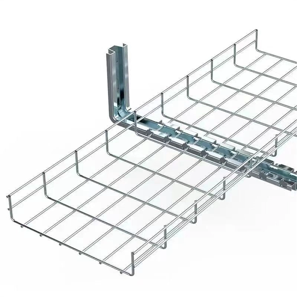
Explore all types of cable trays—ladder, perforated, basket, solid, and channel. Each cable tray type performs a different function and comes in various materials such as aluminum, galvanized steel, and FRP. What is Cable Tray? 1. Non-Metallic What is Cable. Cable tray systems are engineered support structures designed to route, support, and protect insulated electrical cables used for power distribution, control, instrumentation, and communication. Unlike conduit systems, cable trays allow cables to be laid in bundles, improving accessibility, heat. Below are the top 7 types of cable trays and their applications, along with their key advantages. Ladder Type Cable Tray The ladder type cable tray consists of two side rails connected by rungs, allowing excellent airflow around cables. Ladder cable tray is so named because it resembled a ladder. Ladder cable trays are relatively simple in. Selecting the correct cable tray for low voltage system—such as data networking, telecommunications, security, and building automation—is a critical decision that impacts system performance, scalability, and long-term reliability.
[PDF]
Spring knot is used to connect cable tray or trunking to channel. Approved and correct fittings are used. Bonding jumper is installed. Tagging/labelling is provided. Installed containments are free of damages. The purpose of this article is to define the sequence and methodology for the installation of electrical cable trays, cable trunking, cable raceways and boxes, junction and pull boxes. These guidelines are not intended to cover all details or variations in cable ladder and cable tray. Hubbell's NEXTFRAME® Ladder Tray is the effective and widely used cable runway that supports and delivers bundles of cable between cabinets, racks, and closets, along walls, and suspended from ceilings. The Ladder Tray features light, rugged, tubular steel construction. It is designed for. bow fittings, etc. ) Of the tray being mounted. Supports should provide strength and working load sufficient to the load require ents of the cable tray system being supported. Structural building members should never be cut, and cable trays should not be installed in hoist ways or where subject to. Welcome to our comprehensive guide on installing wall brackets for different types of cable trays and cable ladders! In this video, we will walk you through the installation process for four different types of wall brackets, specifically designed for cable trays, mesh cable trays, and cable.
[PDF]
Students trading aid on how best to put an internal 90 degrees bend in steel cable tray. Videos are training aids for City and Guilds 5357 (C and. The bends, tees, crosses, risers and reducers of wire mesh cable tray can be easily and quickly made live at the project by using a bolt cutter. Since the jaws of the bolt cutter drags a layer of zinc across the cut end and forms a protective layer. When a wire cable tray is cut, the fact that a. You can buy a manufactured 90 degree bend or make one on a cable tray bending machine but in this video I show you how to make one using a metal bar. Electrical UK Wiring == 🕐. How many wires can fit in one tray? One should never fill up a tray. The general safety regulations state th/at a person is advised to fill 40-50 percent of the available space. The reason behind this is that the electricity-carrying wires become hot. This involves a few essential steps to ensure a successful bending process. Each example of bends and tee's clearly illustrate proper tray cutting combined with recommended usage of Cablofil accessories. Engineers and contractors in North America and around the world have found. The first step is to mark out the tray (A). Construction of a flat 90° bend (A) The amount of tray lip to be removed is equal to 2, 3/4 the width of the tray, half of this measurement will be removed on either side of the centre line. To remove the lip we can use a small hand grinder (B) or a file.
[PDF]
Step-by-step on-site guide: learn how to plan, mark, support, and install cable trays correctly, from shop drawing approval to final checks. Method Statement installation of Cable Trays and Ladders - Planning Engineer FZE. The Cable Tray system is installed in electrical rooms, plant rooms, and service. Whether you're building a commercial setup or upgrading an industrial plant, proper cable tray installation ensures neat wiring, safe access, and easy maintenance. But before you lay the first tray or clamp down a single cable, you need a solid plan. This guide breaks down the process step by step. In order to get it right, installers are supposed to adhere to a plan that ensures that wires are kept cool and the building is stable. The beginning of success is to review the Bill of Quantities (BOQ) so that. In this post, we will see together how to install cable tray on-site. Firstly, we need an approved shop drawing that shows the cable tray route, its dimensions, installation height, support system, the number of layers of these trays, and the type of systems they will serve. The key requirements for cable tray installation include: Incorrect installation can lead to overheating, cable damage, or system failure. This guide covers the critical steps, from selecting the right electrical cable tray and performing accurate cable fill.
[PDF]

Welcome to our step-by-step guide on installing cable trays! In this video, we'll explore the different types of cable trays available and provide detailed instructions for their installation. Whether you're an experienced electrician or a DIY enthusiast, this. Whether you're building a commercial setup or upgrading an industrial plant, proper cable tray installation ensures neat wiring, safe access, and easy maintenance. But before you lay the first tray or clamp down a single cable, you need a solid plan. This guide breaks down the process step by step. Installing a cable tray system requires careful planning to ensure it can support the weight of the cables and adheres to electrical safety codes. Here is a step-by-step guide on how to install a standard metal cable tray system (e., ladder or perforated type). more. The purpose of this article is to define the sequence and methodology for the installation of electrical cable trays, cable trunking, cable raceways and boxes, junction and pull boxes. The method gives details of how the work will be carried out and what health and safety issues and controls that. Cable tray systems are designed for easy installation and to accommodate power, communications, and signal cabling across a variety of applications. When installed and engineered properly, cable.
[PDF]
Click Systems tab Electrical panel Cable Tray. From the Type Selector, select the cable tray type, with or without fittings. On the Options Bar, specify the width, height, offset, or bend radius. more. I am preparing Cable Tray Drawing where i need to provide Cable tray tags on each tray. for that I have Modified default tray Tag family as per my requirement. I use “Comment” Parameter to to tag my cable trays. in my Model there are many Trays and it is very much lengthy and time consuming task. Understand how to model a cable tray using the systems tab in the electrical section for effective coordination, especially in the electrical room. Learn how to set the middle elevation, draw through the room, avoid conflicting elements, and create a detailed and clear visualization of the cable. Sized for the cable fill of the runs it carries. Above lights, below ducts — coordinate with ceiling plenum. Tees, crosses, and reducers handle every direction change. Noble Desktop's Revit MEP Certification Course covers Revit fundamentals — a strong foundation before specializing in mechanical. Join this channel to get access to perks: This lesson walks through how to start a project and properly set up for Electrical Cable Tray design in Revit 2025. It focuses on template selection, component availability, and basic setup steps. Start With the Right Template Opens a new project and.
[PDF]
Select tray materials and finishes that match the hazard: hot‑dip galvanised steel or stainless for durability; aluminium for lighter loads; FRP for corrosive plants. Pair trays with low‑smoke, halogen‑free cables in occupant areas to reduce toxic fumes. Cable tray installation must comply with specific technical standards to ensure electrical safety, system reliability, and long-term maintainability. This document outlines the key requirements for cable tray layout, installation, and fireproofing in industrial and commercial environments. Route. It involves understanding how Cable Trays and Fire Protection Systems work side-by-side. Cable trays hold the wires for things like power and communication. They seem like separate things, but they need each. Looking at installing a cable tray that runs the length of the room in an Ordinary Hazard Occupancy. The cable tray is less than 18-inches below the sprinkler. However, the cable tray may be centered directly below some. Cable tray systems help organize and support electrical cables efficiently, but improper installation or maintenance can increase the risk of electrical fires. Our tested solutions for cable fire protection can delay the spread of fire in order to minimise the damage sustained. You should consider it as a series of instructions that make the buildings resistant to electrical fires or broken wires. 1 What is NEC Article 392? 1.
[PDF]
In the electrical wiring of buildings, a cable tray system is used to support insulated electrical cables used for power distribution, control, and communication. Cable trays are used as an alternative to open wiring or electrical conduit systems, and are commonly used for cable management in commercial and industrial construction. They are especially useful in situations. TypesSeveral types of tray are used in different applications. A solid-bottom tray provides the maximum protection to cables, but requires cutting the tray or using fittings to enter or exit cables. A deep, solid enclosure for cables i. Common cable trays are made of galvanized,, aluminum, or glass-fiber reinforced plastic. The material for a given application is chosen based on where it will be used. Galvanized tray may b. Combustible cable jackets may catch on fire and cable fires can thus spread along a cable tray within a structure. This is easily prevented through the use of fire-retardant cable jackets, or coatings applied to i.
[PDF]
Cable trays can be used in commercial and industrial buildings Firestopped cable tray penetration with teck cables Fire test in Sweden, showing rapid fire spread through burning of cable jackets from one cable tray to another Cable spreading room at Point TupperOverviewIn the of buildings, a cable tray system is used to support insulated used for power distribution, control, and communication. Cable trays are used as an alternative to open wiring or. Several types of tray are used in different applications. A solid-bottom tray provides the maximum protection to cables, but requires cutting the tray or using fittings to enter or exit cables. A deep, solid enclosure for cables i. Common cable trays are made of galvanized,, aluminum, or glass-fiber reinforced plastic. The material for a given application is chosen based on where it will be used. Galvanized tray may b.
[PDF]
This report analyzes the Eastern European plastic cable trays and ducts market and its size, structure, production, prices, and trade. The Eastern European cable trays market is a critical component of the region's industrial and construction infrastructure, serving as the backbone for organized and secure cable management in energy, telecommunications, and commercial projects. The report provides a strategic analysis of the plastic cable trays and. Europe Steel Cable Trays Market Global Outlook, Country Deep-Dives & Strategic Opportunities (2024-2033) Market size (2024): USD 3. 2 billion · Forecast (2033): 4. 1% Robust infrastructure development initiatives across Europe, driven by urbanization and digital. This report presents a strategic analysis of the plastic cable trays for electrical circuits market in Central and Eastern Europe and a forecast for its development in the medium term. 3 billion in 2025 and is projected to reach USD 5. 4 billion by 2035, registering a compound annual growth rate (CAGR) of 2. 4% over the forecast period. The cable tray market is experiencing robust growth driven by increasing demand for. The trays are essential for cable managing, organizing cables, and conserving the infrastructure carrying electricity. It provides wiring simplicity, system design flexibility, and lower installation cost to the consumer. Almost all types of cables are sorted and maintained with the help of cable.
[PDF]
Schiavetti Tekno, part of Spina Group, is a leading Italian manufacturer of cable trays and accessories for electrical and instrumentation systems. Since 1964, the company has supplied high-quality solutions for industrial cable management in energy, infrastructure, and plant engineering sectors. Recommended maximum length among supports 5,5m. Italy's cable tray manufacturing sector plays a vital role in the nation's infrastructure development. Their expertise ensures reliable cable management systems. Cable tray manufacturers in Italia have established themselves as leaders in cable management solutions, meeting the needs of diverse industries. From energy to construction, these manufacturers deliver high-quality products that ensure efficient and safe electrical wiring management. These products are designed to carry heavier cable loads compared to the. Our cable trays are made of first-class stainless steel (AISI 316 and AISI 304) that prevents corrosion and ensures a good level of resistance. Cable trays from SILTEC are available with a length of 3000 mm. The width varies from 25 mm to 600 mm and the height from 25 mm to 125 mm. Cable trays of a.
[PDF]
CMP CXT type brass indoor and outdoor cable gland for use with all types of screened flexible wire braid (e. CY/SY), or wire braid armour cable. The cable gland provides an environmental seal on the cable outer sheath. Want to discuss this product with one of the CMP Technical Team? Call one of our team now on +44 191 265 7411 We have some exciting things in the pipeline - if you'd like to be the first to know please enter your email address below. Note: Supplied with Locknut & Washer. In summary, CXT is an abbreviation that can stand for various terms depending on the context, and its interpretation can vary across different fields such as technology, business, education, geography, government, law and other specialized areas. Features: Kit Contents: Additional Accessories available (upon request): The information in this datasheet is for. Operating Temp. Entry thread protection rating:. CMP CX Single seal brass cable gland suitable for braided, pliable wire and steel tape armoured cables. Our state-of-the-art cable testing facility ensures that every cable meets the highest standards of quality and compliance through continuous, rigorous testing. Where applicable, cables are.
[PDF]
Basic — 1,000 ft single-mode run indoors with minimal termination: Cable $0. 00/ft, Permits $150, Accessories $100. Total ≈ $2,650–$3,100. 60/ft . Buyers typically pay for fiber optic cable by length, fiber type, and installation complexity. Main cost drivers include cable grade (indoor vs outdoor, armoured), distance, and labor for trenching, splicing, and termination. This guide presents ranges in USD and practical price estimates to help. Do you also provide customisation in the market study? Yes, we provide customisation as per your requirements. To learn more, feel free to contact us on sales@6wresearch. com Any Query? Click Here. Fiber-optic cable materials typically cost $1 to $6 per linear foot, depending on fiber count and cable type. Commercial building installations with 100-200 network drops generally range from $15,000 to $30,000. Content 1 What's the Typical Price Range? 2 1. Fiber Count and Cable Construction 3 2.
[PDF]

In this tutorial, we will show you how to fusion splice two fiber optic strands together in an easy 12 step process. The answer lies in splicing, both fusion and mechanical. Whether you're a professional technician or a DIY enthusiast, understanding the process of fusion splicing fiber optic cables is essential for maintaining high-speed communication networks. - Fiber Instrument Sales What is Fusion Splicing? How fiber optic splicers work, types, what they are used for. Steps to use this equipment and including how to test your fiber splice. The guide covers everything from basic principles of fusion splicing to detailed procedures; it is intended to provide both newbies and professionals with the necessary knowledge and skills. The operation and skills of fiber optic fusion splicing technology can be mainly divided into five steps: fiber stripping, fiber cutting, fiber melting, fiber sleeve, and fiber winding. And tools used for fiber fusion: fusion splicer; fiber cleaver; cable stripper; fiber optic stripper; alcohol;.
[PDF]

While optical power meters are the primary power measurement instrument, optical loss test sets (OLTSs) and optical time domain reflectometers (OTDRs) also measure power in testing loss. TIA standard test FOTP-95 covers the measurement of optical power. This measurement is the basis for loss measurements as well as the power from a source or presented at a receiver. Typically both transmitters and receivers have receptacles for fiber optic connectors, so measuring the. You need a power meter to measure power in a fiber optic system; most power meters come with a screw-on-adapter that matches the connector being tested and a little aid from the network electronics to turn on the transmitter. During the measurement of power, the meter must be set to the proper. Fluke Networks sets the standard in network testing with its advanced range of fiber optic power meters and fault locators, designed to ensure the highest precision in fiber optic meter readings and power evaluations. This is measured in decibels (dB). Splitters, fusion splices, connectors and. To use a power meter for fiber optic testing, always clean connectors first with lint-free wipes or click-to-clean tools. Select the correct wavelength and set your reference. Consistent procedures ensure accuracy.
[PDF]