Insert the end of your fiber optic network line into the fiber optic connector on the converter box. Plug an Ethernet cable into the Ethernet port on the converter box and plug the other end into one of the Ethernet ports on the back of your Ethernet switch. As we speak I just have optic fibre (Community Fibre) connected to my Huawei modem / Linksys Velop which will be connected to a new POE switch (need to identify the best model to be compatible with my optic fibre extension project). The objective is to run 1 or 2 additional optic fibre from the. Connecting a fiber optic switch involves several steps, ensuring compatibility between the switch's ports and the fiber optic cable. Fiber optic switches utilize. Fiber optic cabling is increasingly used to connect network switches and other datacom equipment, especially in long-distance and mission-critical applications. Fiber provides: Increased internet signal bandwidth. Advantages Determine the length of the fiber run and choose either multi mode for runs under 1000 feet or single mode for runs over 1000 feet.
[PDF]

This section includes all PoE enabled Industrial switches available, including managed models and specific application models like vehicle or substation compliant units. Check each product page for other buying options. Shop products from small business brands sold in Amazon's store. Learn more Need help? Industrial-grade PoE switches for demanding. POE Industrial Ethernet units at Plant Technology USA make Power over Ethernet solutions even more efficient and cost effective. Not only are these de. Read more Find the best Industrial Ethernet Equipment for your project. US-based Customer Support. These rugged, fanless platforms support both Gigabit and 10/100 Mbps Ethernet and offer a selection of fixed-fiber, or SFP uplink. We provide a wide range of PoE/PoE+/PoE++ switches with up to 90 W output per port to deliver high-speed data transmission while powering high-power devices over long distances. With an industrial-grade design, our PoE switches provide surge protection of 4 kV per LAN port. Additionally, Smart PoE. In addition to transmitting network data, a PoE Switch has a built-in Power over Ethernet injector to supply up to 100W Power over Ethernet (PoE) to standards-based 802. 3bt compliant devices such as IP cameras, VoIP phones, and wireless access points. When connecting network.
[PDF]

To set up your router for fiber internet quickly, connect the router to your fiber modem, access the router's settings via a web browser, and input the provided ISP credentials. Make sure to update the firmware, configure Wi-Fi security, and customize your network name for. Setting up a fiber internet connection requires understanding key hardware components and following a specific connection sequence to establish your home network. This guide details the necessary physical and digital steps to connect your fiber line and activate your internet service. The fiber. In this guide, we'll walk you through how to connect a fiber optic cable to a router safely and efficiently. Why Use Fiber Optic Internet? Before diving into the setup, let's quickly recap why fiber optics are worth the effort: Lightning-fast speeds (up to 1 Gbps or higher). Here's a simple guide to help you through the process: 1. Check Your Fiber Optic Equipment Before you start, make sure you have the necessary equipment: Fiber Optic Modem (ONT – Optical Network Terminal):. This video makes connecting your fiber optic cable to your router a breeze! We'll guide you through the entire process step-by-step, ensuring a smooth and hassle-free experience. Our Experts are helping user's, who are facing issues with their tech gadgets like Router, Modem and extender.
[PDF]

In a metal box, a wire type equipment grounding conductor can be attached to the box with a ground screw or clip and terminated to the switch or receptacle in the box. Connecting the receptacle grounding terminal to the metal box ensures an effective ground-fault current path. The basic rule achieves this through an equipment grounding jumper; four exceptions. A main bonding jumper is required to bond the service disconnect enclosure to the service neutral conductor [250. Not all boxes are metal or provide. The main bonding jumper bonds the neutral conductor to the equipment grounding conductor, enabling proper operation of overcurrent protective devices. Neutral conductors must be properly sized based on the load and installation method, with specific requirements for conductors in parallel or. According to the National Electrical Code (NEC), this connection is made between the grounded conductor (typically the neutral) and the equipment grounding conductor (EGC) system at the service equipment. Proper location and sizing are not just best practices; they are essential for ensuring that. NEC Article 250 is dedicated entirely to grounding and bonding, outlining the specific conductors and connections required. Grounding Electrode Conductor (GEC): This is the wire that connects the grounding electrode (the rod) to the grounding bus bar in the main electrical panel.
[PDF]

This diagram shows how the RJ45 cable is connected to the PoE switch, allowing it to power devices such as IP phones and cameras. In this article, we will explore the wiring diagram for a PoE switch, which provides a visual representation of how the switch connects to various devices. Each device is represented by a. Do you want to set up a new computer network in your home or office? Chances are, you'll need a Poe switch wiring diagram. Not only do these diagrams provide all the information you need to install a network, but they also help make the process easier and more efficient. For those who don't know. A PoE Switch, also known as Power over Ethernet Switch, is a network device that allows users to power and connect devices such as IP cameras, VoIP phones, and wireless access points. In essence, a PoE Switch can be described as regular switch with added ability of Power over Ethernet which allows. PoE technology enables the transmission of both data and power over a single ethernet cable, simplifying network setups and eliminating the need for additional power sources. This is particularly useful in scenarios where devices like IP cameras, wireless access points, or VoIP phones need to be. Here, you can see the details, Keep the copper strips towards your face and count the pin number or pin position from left to right. The T568B also has a total of eight pins and sight different colors.
[PDF]
Let us now see the differences between PoE and Non-PoE Switch. We will take some important parameters and list out the differences. Before understanding PoE, let us quickly take a look at a Network Switch. An Ethernet Switch or a Network Switch is a device that has several RJ45 Portsto connect many devices. The switch will transmit data between ports using the destination MAC Address in the Ethernet Frame. If you consider the OSI Model, Switches are Layer 2 or Data Link Layer d. Now that we have seen the differences between PoE and Non-PoE Switch, the question is which one should you buy? Assume your devices are all non-PoE i.e., computers, laptops, and other networking devices with power supply. In this, you are better off with a regular non-PoE Switch. You can save a lot on the switch but in our frank opinion, this is no.
[PDF]
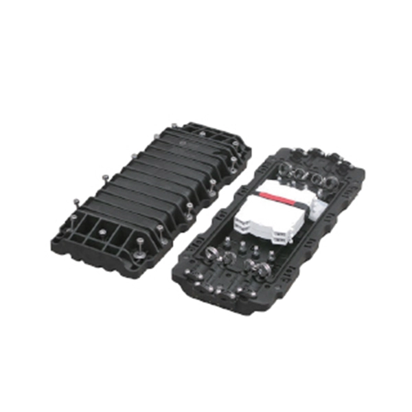
Capable of serving up to 4/8 subscribers, it functions as an essential termination point in FTTx communication networks, accommodating fiber splicing, splitting, and distribution effectively. Elevate your telecommunications infrastructure with the COMX Fiber Distribution Box (FDB), expertly designed for seamless fiber management and distribution. This robust FDB integrates a connectorized splitter, optimizing fiber connectivity and facilitating swift deployment in both indoor and. The FDB-12C Fiber Optic Distribution Box is an outdoor enclosure designed for splicing, splitting, and drop cable connectivity to meet the demands of high-density fiber-to-the-home (FTTH) and fiber-to-the-curb (FTTC) access networks. With capacity for 12 customer connections in a compact IP55 wall. Indoor FTTH Fiber Distribution Box, optical fiber distribution box is used for the fusion splicing, splitting, wiring transmission, and other functions of the optical transmission terminal. It can effectively terminate, protect and manage the optical cable. It is necessary equipment in network. Fiber optic cross connect cabinet, also known as fiber distribution hub (FDH). It play a crucial role in determining the network coverage capacity of a fiber optic network. It provides a structured environment for routing cables, managing splices, and accommodating termination modules. FDBs are used to organize incoming and outgoing cables.
[PDF]
Connect the fiber optic cable: Attach the fiber optic cable's connector to the transceiver module on the switch. Make sure the connector type (e., SC, LC) matches the transceiver module. Fiber optic cabling is increasingly used to connect network switches and other datacom equipment, especially in long-distance and mission-critical applications. Fiber provides: Increased internet signal bandwidth. Most modern fiber-enabled network switches require an SFP transceiver module. This document describes how to troubleshoot fiber optic interfaces by addressing some of the fiber optic module and cabling specifications. There are no specific requirements for this document. The information in this document is based on all Catalyst 9000 Series switches. This includes Doppler. Connecting a switch to a fiber optic network involves several steps and requires specific equipment to ensure a successful and efficient connection. If you're looking to learn how to configure fiber optics on a Cisco switch, it's important to first configure the switch settings so it's ready for fiber optics. Fiber optic switches utilize. Other than entry level network switches, most of today's network switches include one or more GiBC (Gigabit Converter) or SFP (Small Form-factor Pluggable) slots. SFP modules insert into these slots and and require two strands of fiber, typically duplex Using multi mode fiber (for runs under 1000.
[PDF]
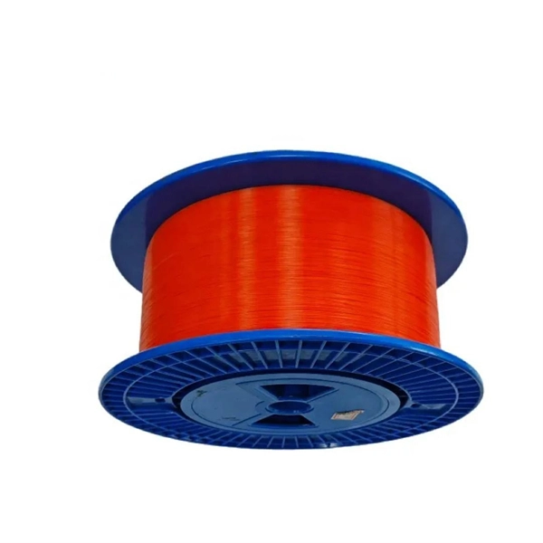
This beginner-friendly guide will walk you through the step-by-step process of fiber optic cable installation for each method, highlighting best practices, tools, and considerations. Proper connection of fiber optic cables is essential to harness these benefits fully, as even minor errors can lead to significant performance issues like signal loss. This article will guide you through the necessary tools, materials, and methods on how to connect fiber optic cables effectively. Starting with site surveys and permissions, to installing fiber optic cable and emphasizing the process as a key stage in mastering fiber optic installation, to the careful handling of cables and high-stakes splicing, each stage is critical. Discover the exact steps, adhere to stringent safety. Single family homes, apartments, condominiums and other multi-dwelling units are increasingly wired with fiber optic cable to future-proof installations and create more reliable, higher-bandwidth and faster speed network and video infrastructures. The processes. Running fiber internally involves extending this high-speed link from the service entry point to a centralized location, such as a dedicated media closet or network rack. This DIY effort is undertaken to maximize performance, improve aesthetics, or relocate the Optical Network Terminal (ONT) to a.
[PDF]
Follow these steps to connect your WiFi router or modem using the TP-Link TL-POE10R POE Splitter: Plug one end of a Cat6 Ethernet cable into a POE port on the POE switch. This cable will carry both data and power. Connect the other end to the Ethernet input port of the TP-Link POE. We can use TL-POE150S and TL-POE10R to expand the network for the place where power line can not reach or there is no outlet. In the topology shown as above, both TL-POE10R and the device which connect to it do not need external power adapter, the TL-POE150S can provide power supply and data for. In this video, we dive into how to use the TP-Link TL-POE10R POE Splitter to supply power and LAN connectivity to a WiFi router, modem, or access point from a CCTV system POE switch. This powerful device simplifies your network setup by delivering both power and data through a single Ethernet. Connecting TP-Link cameras to a POE switch is a seamless, plug-and-play process that powers and networks your security system in minutes. Simply link the camera to the POE switch using a single Ethernet cable—handling both data and power—then configure via the TP-Link app for live viewing and. The Injector sends power and data over the Ethernet cable to the Splitter. Then the Splitter separates the data and power back into two cables and delivers them to the remotely located access point or other network device that requires a 5/9/12-volt power input. 2 Features Complies with IEEE.
[PDF]

Welcome to our channel! In this video, we'll walk you through the process of wiring a home distribution box with a detailed connection diagram. Whether you're an electrician or a DIY enthusiast, this guide will help you understand the basics of home electrical. This guide provides step-by-step instructions for connecting a distribution box and highlights key factors to consider during installation. What Is a Distribution Box? A distribution box, also known as an electrical distribution board, is a critical component in electrical systems. more Welcome to our. Start by positioning the control panel within 30 feet of both the generator and the main service box. This ensures minimal voltage drop and straightforward conduit routing. Connect the neutral and ground conductors to their. A manual transfer switch is installed next to the main service panel to override the normal electrical service with power from a backup generator during a power outage. Very few homeowners can afford or consider it necessary to supply power to all of the homes electrical devices, fixtures and appliances in the event of a power.
[PDF]

Learn how to safely wire a single-pole (one way) light switch in this beginner-friendly tutorial. Whether you're replacing an old switch or doing your first DIY electrical project, this guide will walk you through every step — no experience needed!. more. This page contains wiring diagrams for household light switches and includes: a switch loop, single-pole switches, light dimmer, and a few choices for wiring an outlet/switch combo device. That's because virtually all light switches that control 120-volt fixtures are single-pole switches. Most light switches are also single-throw, which. Summary: Fully explained wiring diagrams and photos show how to wire switches including: single switches, 3-way switches, 4-way switches, and dimmer switches. and Be Sure to Subscribe! Make sure the circuit power has been turned off, and mark the circuit breaker or fuse to indicate that work is. A distribution board or distribution box is where the main power supply is distributed to multiple loads. And all the switching and protective devices are installed in the distribution box. Single Phase Distribution Box generally consists of Double Pole MCBs, Single Pole MCBs, and RCCBs. Wiring a single light switch may seem like a daunting task, but with the right tools, a bit of patience, and this comprehensive guide, you'll be able to tackle this DIY project with confidence. Remember, while this guide provides detailed instructions, always prioritize safety and consult a.
[PDF]

This guide delves into the structure and working principle of fiber optic connectors and outlines the critical steps for creating a successful connection. Proper connection of fiber optic cables is essential to harness these benefits fully, as even minor errors can lead to significant performance issues like signal loss. This article will guide you through the necessary tools, materials, and methods on how to connect fiber optic cables effectively. This guide will explain the entire set of activities involved in installing Fiber optic cable contractors -from the early planning stage right through testing-for facility managers, IT teams, and low-voltage contractors to build high-performance networks safely and efficiently. The processes. However, working with fiber requires specialized skills and equipment to connect cables properly. This guide will walk you through the complete process of connecting fiber optic cable. Before connecting any fiber cable, you need to assemble the proper preparation tools: With the right tools in. The Fiber Optic Association, Inc. (FOA) was founded in 1995 to help develop the workforce to build the fiber optic networks to support a rapid expansion in communications and the Internet.
[PDF]
Shop Upgraded 10 Port 10 100mbps Poe Switch With 8 Port at best prices at Desertcart Honduras. ✓FREE Delivery Across Honduras. ✓EASY Returns & Exchange. FS 100G Switches offer high programmability and scalability, designed for large enterprises and hyper-converged infrastructure (HCI) networks. Learn more!. EXTENDED RANGE - Enjoy data transmission up to 250m, ensuring your devices stay connected even at a distance. ENHANCED SECURITY - One-Key VLAN isolates ports for optimized bandwidth and improved network security. ROBUST COMPATIBILITY - Supports IEEE 802. 3af/at standards, delivering up to 30W per. FS offers PoE+/PoE+ Switches with 1G/2. Plug and play, quick deployment. Ethernet cables transmit data and power, reducing wiring difficulty.
[PDF]

Use the SWD or JTAG interface to connect the ST-Link v2 to the STM32 microcontroller. Download and install STM32CubeIDE or another compatible IDE. Install the ST-Link USB driver (available on the STMicroelectronics. The ST-LINK/V2 is an in-circuit debugger/programmer for the STM8 and STM32 microcontrollers. The single wire interface module (SWIM) and the JTAG/serial wire debugging (SWD) interfaces facilitate communication with any STM8 or STM32 microcontroller operating on an application board. ATOLLIC, IAR and KEIL Integrated Development Environments for. How do you use SWD (Serial Wire Debug) for debugging STM32? - HackMD Using SWD (Serial Wire Debug) for debugging STM32 microcontrollers is a powerful way to monitor and control code execution, inspect registers, and analyze faults. Here's a step-by-step guide to set up and use SWD effectively: 1. In addition. This small guide will explain how to connect your debugger to your development board. There are two commonly used connectors which expose only the SWD (Serial Wire Debug) interface or the full JTAG interface. If you are using one of ST's official Nucleo or Discovery boards, you do not have to. To upload a program to a chip from Thomson Semiconductor you need an ST-Link programmer device to connect your PC. Thompson sells branded programmers, adaptors and cables. We'll use an inexpensive ST-LinkV2. They look like AVR programmers but you need to read the pinouts on the side.
[PDF]