
In today's video, we'll be unboxing the 9-Port Power Supply Box and demonstrating how to connect the cables to provide power to CCTV cameras. A CCTV power supply box sends power to all your cameras from one place. It helps keep things neat and makes your system easier to manage. In this guide, you'll learn how to install it step by step, choose the right type, avoid common problems, and keep your system running safely. Power supply boxes for CCTV are typically used in multi-camera installations instead of using single power adapters for each camera. The process is almost exactly the same if you. Installers of surveillance systems may simply control the power to various CCTV cameras using a CCTV power supply box, also known as a power distribution box (usually at the location of the DVR). This enables a cleaner camera installation. Surge protection can be accomplished in two ways. The power supply box is specifically used to transfer power requirements for all cameras plugged in on the system, to work. Security cameras use RG59U coax siamese wire or CAT5e networking cable to transmit video. Whether you are installing a power box for a new or existing camera system, it is important to understand how to connect cameras to a CCTV Power Supply Box. DC current is polarized meaning it has two leads, a.
[PDF]

Every temporary power distribution box has several important components that work together to deliver safe, efficient power: These boxes use either 120/240 VAC single-phase or 120/208 or 277/480 VAC three-phase power sources. Temporary power distribution boxes are a budget-friendly way to supply electricity to a remote area. You can use them to power electrical equipment, lighting systems and more. Compared to other temporary power solutions, a power distribution box provides utility, safety and efficiency at an. Temporary power distribution boxes provide a safer way to manage power while keeping your workspace tidy. These versatile units work great for construction sites, entertainment events, and disaster recovery operations. Modern solutions rely on portable. Whether you need an industrial portable power station, a complete jobsite power station, or help managing temporary wiring and distribution, this will help you stay compliant with all the necessary requirements. Getting the selection wrong means more than inconvenience—it can mean shutdowns, damaged machinery, or worse.
[PDF]
Insert the end of your fiber optic network line into the fiber optic connector on the converter box. Plug an Ethernet cable into the Ethernet port on the converter box and plug the other end into one of the Ethernet ports on the back of your Ethernet switch. As we speak I just have optic fibre (Community Fibre) connected to my Huawei modem / Linksys Velop which will be connected to a new POE switch (need to identify the best model to be compatible with my optic fibre extension project). The objective is to run 1 or 2 additional optic fibre from the. Connecting a fiber optic switch involves several steps, ensuring compatibility between the switch's ports and the fiber optic cable. Fiber optic switches utilize. Fiber optic cabling is increasingly used to connect network switches and other datacom equipment, especially in long-distance and mission-critical applications. Fiber provides: Increased internet signal bandwidth. Advantages Determine the length of the fiber run and choose either multi mode for runs under 1000 feet or single mode for runs over 1000 feet.
[PDF]
Wiring a 3-way junction box involves connecting three separate wires: the hot wire, the traveler wire, and the neutral wire. Here is a step-by-step guide on how to wire a 3-way junction box. In a 3-way junction box, multiple wires can be joined together for the purpose of distributing power or connecting different electrical devices. Whether you are a professional electrician or a DIY enthusiast, understanding how to properly wire a 3-way junction box is essential for maintaining. In this article, we'll take a look at what you need to do in order to wire a 3-way junction box and provide you with some useful tips to make the process easier. In this comprehensive guide, we. Learn how to install a junction box safely, from choosing the right box and mounting it correctly to making secure splices and following basic code-safe practices. To install a junction box correctly, choose a box that matches the wiring method and environment, mount it securely, bring cables in. A three wire junction box is an essential component in electrical installations that allows for the connection and distribution of electrical wires. It provides a safe and convenient way to connect multiple wires, ensuring proper electrical continuity and reducing the risk of electrical hazards. We may be compensated if you purchase through links on our website. Our team is committed to delivering honest, objective, and independent reviews on home.
[PDF]

Welcome to our channel! In this video, we'll walk you through the process of wiring a home distribution box with a detailed connection diagram. Whether you're an electrician or a DIY enthusiast, this guide will help you understand the basics of home electrical. This guide provides step-by-step instructions for connecting a distribution box and highlights key factors to consider during installation. What Is a Distribution Box? A distribution box, also known as an electrical distribution board, is a critical component in electrical systems. more Welcome to our. Start by positioning the control panel within 30 feet of both the generator and the main service box. This ensures minimal voltage drop and straightforward conduit routing. Connect the neutral and ground conductors to their. A manual transfer switch is installed next to the main service panel to override the normal electrical service with power from a backup generator during a power outage. Very few homeowners can afford or consider it necessary to supply power to all of the homes electrical devices, fixtures and appliances in the event of a power.
[PDF]

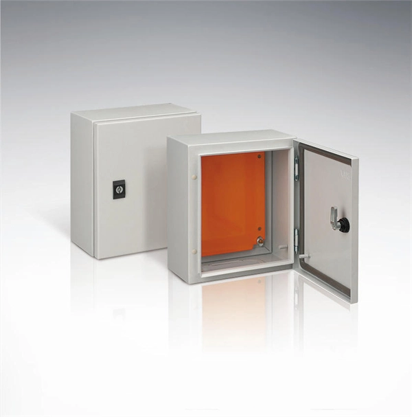
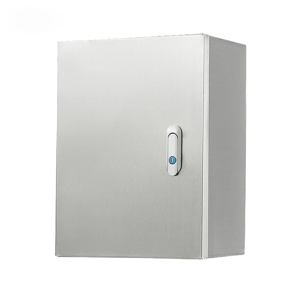
Connect the input and output wires to the corresponding terminals of the distribution box. This step is very crucial and can not bear any faults!. In this video, we'll walk you through the process of wiring a home distribution box with a detailed connection diagram. more Welcome to our channel! In this video. Before installation, it's important to know what makes up a distribution box. Let's break it down into two main parts: the outer shell and the electrical parts inside. The enclosure protects the electrical components from water, dust, and damage. When choosing one, check the IP or NEMA rating. A. A neutral link is used to distribute a neutral supply to all the output loads. When single-pole MCBs are used for output loads, the neutral wire of the loads is connected to the neutral link. Follow this guide for a clear and safe connection process: Before starting, always ensure the main power is turned off to avoid electrical shock. It is usually equipped with circuit breakers, fuses, terminal connectors, and other components. It is mainly used to isolate fault circuits, prevent overload, and ensure the safe operation of. Connection method: Each switch takes a wire from the incoming point and connects it to the incoming end of the switch, or uses parallel connection to reduce the difficulty of wiring. Wiring Direction: Wiring between the main circuit breaker and each branch circuit breaker in the box generally.
[PDF]
Connect the phase and neutral wires from the input power supply to the input of the Main MCB. If you use a DP MCB for output load then connect both phase and neutral from the output of the RCCB to the input of the Load. This guide provides step-by-step instructions for connecting a distribution box and highlights key factors to consider during installation. What Is a Distribution Box? A distribution box, also known as an electrical distribution board, is a critical component in electrical systems. It serves as a central hub for distributing electricity throughout a building, ensuring that power is delivered safely and efficiently to all the required locations. It is usually equipped with circuit breakers, fuses, terminal connectors, and other components. It is mainly used to isolate fault circuits, prevent overload, and ensure the safe operation of. How to wire a household distribution box? How to pg clamps. When it comes to decoration, many friends like to do it themselves. However, when encountering water and electricity and other links that have a greater impact on the overall decoration, you must do your homework and not implement it. In this video, we'll walk you through the process of wiring a home distribution box with a detailed connection diagram. Whether you're an electrician or a DIY enthusiast, this guide will help you understand the basics of home electrical distribution.
[PDF]

In a metal box, a wire type equipment grounding conductor can be attached to the box with a ground screw or clip and terminated to the switch or receptacle in the box. Connecting the receptacle grounding terminal to the metal box ensures an effective ground-fault current path. The basic rule achieves this through an equipment grounding jumper; four exceptions. A main bonding jumper is required to bond the service disconnect enclosure to the service neutral conductor [250. Not all boxes are metal or provide. The main bonding jumper bonds the neutral conductor to the equipment grounding conductor, enabling proper operation of overcurrent protective devices. Neutral conductors must be properly sized based on the load and installation method, with specific requirements for conductors in parallel or. According to the National Electrical Code (NEC), this connection is made between the grounded conductor (typically the neutral) and the equipment grounding conductor (EGC) system at the service equipment. Proper location and sizing are not just best practices; they are essential for ensuring that. NEC Article 250 is dedicated entirely to grounding and bonding, outlining the specific conductors and connections required. Grounding Electrode Conductor (GEC): This is the wire that connects the grounding electrode (the rod) to the grounding bus bar in the main electrical panel.
[PDF]

How to hardwire a Self-Regulating heat cable into a junction box, with a tutorial of the final end seal. First thing, get the sealing ring and connect it onto the connector body. Make sure it gets onto the very e. Safety comes first, and clear info makes it doable. Know Your. We'll show you how to size the heater, run a new, safe 240-volt circuit and install a programmable thermostat. Most homes have sufficient capacity for the new circuit in the service. If you're working with heating cables, understanding how to connect them safely and efficiently is crucial. In this guide, we'll break down the steps in simple terms. Whether you're a DIY enthusiast or a professional, this article is here to help. Stay safe and ensure proper installation with these. I need help wiring an electric furnace with heat elements. I ran number 6 wire with ground from my 100 amp service box where I installed a 60amp double pole breaker. The furnace comes with an other set of breakers one 60amp and one. A distribution board or distribution box is where the main power supply is distributed to multiple loads. Single Phase Distribution Box generally consists of Double Pole MCBs, Single Pole MCBs, and RCCBs.
[PDF]
The cost to install fiber optic cable ranges from $1. 50 to $42 per foot, with installation costs accounting for 60-80% of total project expenses. According to the Fiber Broadband Association's 2025 report, median costs are $8 per foot for aerial builds and $18 per foot for. Homeowners and businesses typically pay for fiber optic cable installation based on distance, conduit needs, and labor. The main cost drivers include material type, run length, trenching or aerial work, and any required permits or inspections. This article outlines cost expectations. The initial cost of installing fiber optic cables can vary depending on the chosen installation method and specific project requirements. fiber projects, we've assembled current material rates, labor burdens, and hidden fees. Whether you need singlemode, armored, or indoor plenum, this guide gives you the exact cost per foot of fiber optic cable —. Fiber optic cable installation costs between $1,500 and $7,000 for your home, with prices varying by cable length and installation method. The installation type you choose and the layout of your property determine the total labor and materials needed for your project.
[PDF]

In this video, we'll walk you through the process of wiring a home distribution box with a detailed connection diagram. This guide provides step-by-step instructions for connecting a distribution box and highlights key factors to consider during installation. What Is a Distribution Box? A distribution box, also known as an electrical distribution board, is a critical component in electrical systems. Whether you're an electrician or a DIY enthusiast, this guide will help you understand the basics of home electrical distribution. more Welcome to our channel! In this video. Correct wiring methods for circuit breakers within distribution boxes are fundamental to ensuring electrical safety and compliance with established codes. The distinction between 1P and 2P circuit breakers plays a pivotal role in determining the appropriate protection level for various circuits. Single phase DB box wiring involves connecting the live, neutral, and earth wires to their respective terminals in the distribution board. Wiring a single-phase distribution board (DB) box is a fundamental task for. A residential breaker box, or load center, is the heart of a home's electrical distribution system. This panel routes power from the utility service to every circuit while housing circuit breakers that provide overcurrent protection. Installing or replacing a load center is a complex task involving.
[PDF]

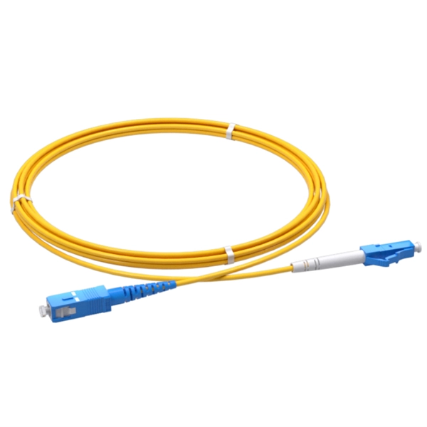
In this guide, we'll walk you through exactly how to splice fiber without a fusion splicer, covering the tools you need, the step-by-step process, performance specs, and common mistakes to avoid. By the end, you'll be equipped to make clean, low-loss connections in any field scenario. What is a. Infield installations, splicing is a faster and more efficient method and is used to restore fiber optic cables when a buried cable is accidentally severed. There are 2 methods of splicing, mechanical or fusion. Both methods provide much lower insertion loss compared to fiber connectors. Experts who add quality contributions will have a chance to be featured. Instead, it uses a small plastic or metal device to hold the fiber ends tightly together. A special index-matching gel is often used inside the splice to help light pass through the connection. The pre-terminated fiber optical cable is produced in the factory. The connector is made and well test. Simply plug and play. However, the length is fixed with a pre-made fiber optical cable. You can't get all the length you need. In this video, you will see how to use the LC coupler to join two. This blog post looks at the various options available to installers for responding to these issues; from splicing and field-fit connectors to factory-terminated or pre-connectorization. Splicing in the Field When fiber was first deployed, it was mechanically spliced, meaning that fibers were.
[PDF]
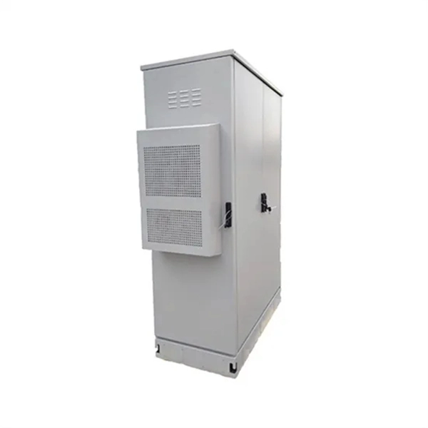
Capable of serving up to 4/8 subscribers, it functions as an essential termination point in FTTx communication networks, accommodating fiber splicing, splitting, and distribution effectively. Elevate your telecommunications infrastructure with the COMX Fiber Distribution Box (FDB), expertly designed for seamless fiber management and distribution. This robust FDB integrates a connectorized splitter, optimizing fiber connectivity and facilitating swift deployment in both indoor and. The FDB-12C Fiber Optic Distribution Box is an outdoor enclosure designed for splicing, splitting, and drop cable connectivity to meet the demands of high-density fiber-to-the-home (FTTH) and fiber-to-the-curb (FTTC) access networks. With capacity for 12 customer connections in a compact IP55 wall. Indoor FTTH Fiber Distribution Box, optical fiber distribution box is used for the fusion splicing, splitting, wiring transmission, and other functions of the optical transmission terminal. It can effectively terminate, protect and manage the optical cable. It is necessary equipment in network. Fiber optic cross connect cabinet, also known as fiber distribution hub (FDH). It play a crucial role in determining the network coverage capacity of a fiber optic network. It provides a structured environment for routing cables, managing splices, and accommodating termination modules. FDBs are used to organize incoming and outgoing cables.
[PDF]

Join Jake from Omnitron in this comprehensive tutorial. Understand the nuances of single-mode and multimode fibers, and how to bridge the gap using media converters. Enhance your tech knowledge and. But what happens when you need to connect an existing multi-mode campus network to a new single-mode service provider link? You can't just splice them together. This is where fiber conversion comes in. This guide will break down the professional methods to achieve seamless single-mode to multi-mode. Single-mode (SMF) and multi-mode fiber (MMF) use different core sizes, sources and wavelengths. These differences determine which transceivers work with which fiber and how far signals can travel. Let's analyze the differences between multimode and single-mode fiber to understand why networks require fiber mode conversion and. How can we convert the multimode to a singlemode fiber system? This complete guide will provide answers to these questions. That is because SMF and MMF have. There are two main types of fiber optic cables: single mode and multimode. Although they can do the same job in some instances, the different construction methods make each of them better suited to certain tasks and budgets. What if end B is located in another building, dozens of kilometers far away from end A? Or end B equipment is single-mode or must use a single-mode fiber connection? In the former case, you.
[PDF]

This guide provides a complete framework for understanding, identifying, and planning MPO connector gender in data center environments. Visually, male and female MPO connectors are easy to distinguish: male connectors feature two alignment pins (PIN pins), while female connectors have corresponding holes instead of pins. An MPO connection is made between a male and female connector to make sure that there is proper alignment. Interfaces on active MPO equipment, such as transceivers are usually male, so any MPO trunk cable. In modern data centers and high-density fiber optic networks, MPO (Multi-Fiber Push-On) connectors have become an essential solution for achieving fast, reliable, and scalable connectivity. You will discover the physical distinctions between male and female connectors and how to develop a gender strategy for your infrastructure, which gender connects. Whether you're supporting parallel optics like 100G SR4 or densifying an optical distribution frame (ODF), MPO is now a cornerstone of network design. This article explains: And a practical checklist to design MPO systems that scale cleanly. If you only remember one thing: MPO is a multi-fiber. In MPO and MTP fiber connector systems, Male vs Female and Pin vs No-Pin describe the same core engineering attribute: the presence or absence of alignment pins on the MT ferrule. Unlike single-fiber connectors such as LC or SC, this distinction is not optional terminology but a mandatory.
[PDF]