
This is the most fundamental ring topology, formed by connecting three or more switches in a closed loop using fiber optic cables. Data can flow in either direction, allowing the network to recover quickly if a link fails. If you have multiple Ethernet switches that need to be connected over long distances, fiber is obviously a preferred choice. Moreover, when it comes to bandwidth, no currently available technology is better than single-mode fiber. It can provide significantly higher bandwidth and carry more data. A single 6 strand fiber can only connect 3 switches back to the core. How many switches do you plan to connect? A star is great for a limited number of switches. I have maybe 20 coming back to my cores. Rings are generally not done anymore, but I think that is for bandwidth as much as anything else. The mainline of the fiber optic LAN directly connects to the switch, then to the router. The connection between two or more Ethernet switches in a certain way (Uplink port, etc. ) is called the cascade. All switches have two fiber ports. Is the best way to have fiber backbone switch and connect fiber channel from every switch to the backbone? Or connect switch 1 to switch 2 to switch 3 to. switch 12 to switch 1 again? Thanks! Let's get some. I need to connect 4 Floor Building with 4 Cisco 2960 - 48 ports switch each other and it needs to be through a fiber. This design ensures data can travel in both directions.
[PDF]

When you connect two 1000BASE-T switches with SFP ports to achieve Gigabit Ethernet, there are two methods: through standard Ethernet cable plugged into the built-in Ethernet ports of each switch, or use the SFP ports with a copper SFP module. 🎥 In this video, I show you how to connect two different branded switches using SFP modules and fiber optic cables. Whether you're using Cisco, Planet, TP-Link, D-Link, Ubiquiti, or any other brand — the key is understanding SFP compatibility. Before moving ahead, let us discuss some basics about standard Ethernet cables and 1000BASE-T (IEEE 802. Network topology refers to the way in which the links and nodes of a network are arranged in relation to each other. What Is a 10Gb SFP Module? A 10Gb SFP (Small Form-factor Pluggable) module is a compact, hot-swappable transceiver used to establish high-speed fiber. Did you swap one of the fiber connectors at one of the endpoints? Meaning, take off the housing of the fiber connector, and swap a and b. You'll find SFP / SFP+ specs on the datasheets for the switches. They're free to view and download from Cisco. Cisco also publish a GBIC /. Most modern fiber-enabled network switches require an SFP transceiver module featuring a duplex (two strand) multimode OM3 or duplex single mode OS2 connection with LC connectors. Direct attach cables with pre-terminated SFP connections may also be used. Download the Application PDF SFP transceiver.
[PDF]

Join Jake from Omnitron in this comprehensive tutorial. Understand the nuances of single-mode and multimode fibers, and how to bridge the gap using media converters. Enhance your tech knowledge and. But what happens when you need to connect an existing multi-mode campus network to a new single-mode service provider link? You can't just splice them together. This is where fiber conversion comes in. This guide will break down the professional methods to achieve seamless single-mode to multi-mode. Single-mode (SMF) and multi-mode fiber (MMF) use different core sizes, sources and wavelengths. These differences determine which transceivers work with which fiber and how far signals can travel. Let's analyze the differences between multimode and single-mode fiber to understand why networks require fiber mode conversion and. How can we convert the multimode to a singlemode fiber system? This complete guide will provide answers to these questions. That is because SMF and MMF have. There are two main types of fiber optic cables: single mode and multimode. Although they can do the same job in some instances, the different construction methods make each of them better suited to certain tasks and budgets. What if end B is located in another building, dozens of kilometers far away from end A? Or end B equipment is single-mode or must use a single-mode fiber connection? In the former case, you.
[PDF]
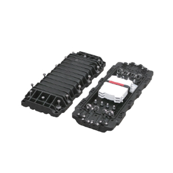
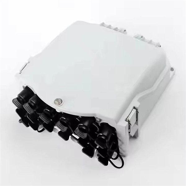
Capable of serving up to 4/8 subscribers, it functions as an essential termination point in FTTx communication networks, accommodating fiber splicing, splitting, and distribution effectively. Elevate your telecommunications infrastructure with the COMX Fiber Distribution Box (FDB), expertly designed for seamless fiber management and distribution. This robust FDB integrates a connectorized splitter, optimizing fiber connectivity and facilitating swift deployment in both indoor and. The FDB-12C Fiber Optic Distribution Box is an outdoor enclosure designed for splicing, splitting, and drop cable connectivity to meet the demands of high-density fiber-to-the-home (FTTH) and fiber-to-the-curb (FTTC) access networks. With capacity for 12 customer connections in a compact IP55 wall. Indoor FTTH Fiber Distribution Box, optical fiber distribution box is used for the fusion splicing, splitting, wiring transmission, and other functions of the optical transmission terminal. It can effectively terminate, protect and manage the optical cable. It is necessary equipment in network. Fiber optic cross connect cabinet, also known as fiber distribution hub (FDH). It play a crucial role in determining the network coverage capacity of a fiber optic network. It provides a structured environment for routing cables, managing splices, and accommodating termination modules. FDBs are used to organize incoming and outgoing cables.
[PDF]

How to hardwire a Self-Regulating heat cable into a junction box, with a tutorial of the final end seal. First thing, get the sealing ring and connect it onto the connector body. Make sure it gets onto the very e. Safety comes first, and clear info makes it doable. Know Your. We'll show you how to size the heater, run a new, safe 240-volt circuit and install a programmable thermostat. Most homes have sufficient capacity for the new circuit in the service. If you're working with heating cables, understanding how to connect them safely and efficiently is crucial. In this guide, we'll break down the steps in simple terms. Whether you're a DIY enthusiast or a professional, this article is here to help. Stay safe and ensure proper installation with these. I need help wiring an electric furnace with heat elements. I ran number 6 wire with ground from my 100 amp service box where I installed a 60amp double pole breaker. The furnace comes with an other set of breakers one 60amp and one. A distribution board or distribution box is where the main power supply is distributed to multiple loads. Single Phase Distribution Box generally consists of Double Pole MCBs, Single Pole MCBs, and RCCBs.
[PDF]

Welcome to our channel! In this video, we'll walk you through the process of wiring a home distribution box with a detailed connection diagram. Whether you're an electrician or a DIY enthusiast, this guide will help you understand the basics of home electrical. This guide provides step-by-step instructions for connecting a distribution box and highlights key factors to consider during installation. What Is a Distribution Box? A distribution box, also known as an electrical distribution board, is a critical component in electrical systems. more Welcome to our. Start by positioning the control panel within 30 feet of both the generator and the main service box. This ensures minimal voltage drop and straightforward conduit routing. Connect the neutral and ground conductors to their. A manual transfer switch is installed next to the main service panel to override the normal electrical service with power from a backup generator during a power outage. Very few homeowners can afford or consider it necessary to supply power to all of the homes electrical devices, fixtures and appliances in the event of a power.
[PDF]

Learn how to properly install a pigtail connector in just a few easy steps. No description has been added to this video. Enjoy the videos and music you love, upload original content, and share it all with friends, family, and the world on YouTube. Pigtail connections are most frequently used to ground a switch or electrical outlet and for electrical devices that need to connect to multiple circuit wires. They also come in handy to lengthen circuit wires that are too short to reach a device. A pigtail is composed of three strands of wire. A pigtail connector is a short length of insulated electrical wire that is pre-attached to a device, terminal, or fixture, serving as a flexible bridge between the fixed wiring system and the component. Whether you are a DIY enthusiast or someone facing an electrical issue, understanding how to replace a pigtail connector can be invaluable. This article will walk you through the necessary steps and provide. This is where quality automotive connector replacement steps in. Often, rather than pay thousands of dollars for an entire harness, you can simply replace the damaged connector by a careful de-pin/re-pin or an accurate wire repair. Want more automotive electrical wire repair videos? Click Here Hear. The National Electrical Code (NEC) requires a pigtail to be at least six inches long. Although this standard applies to house wiring, we can use the same for vehicle wiring.
[PDF]
Spring knot is used to connect cable tray or trunking to channel. Approved and correct fittings are used. Bonding jumper is installed. Tagging/labelling is provided. Installed containments are free of damages. The purpose of this article is to define the sequence and methodology for the installation of electrical cable trays, cable trunking, cable raceways and boxes, junction and pull boxes. These guidelines are not intended to cover all details or variations in cable ladder and cable tray. Hubbell's NEXTFRAME® Ladder Tray is the effective and widely used cable runway that supports and delivers bundles of cable between cabinets, racks, and closets, along walls, and suspended from ceilings. The Ladder Tray features light, rugged, tubular steel construction. It is designed for. bow fittings, etc. ) Of the tray being mounted. Supports should provide strength and working load sufficient to the load require ents of the cable tray system being supported. Structural building members should never be cut, and cable trays should not be installed in hoist ways or where subject to. Welcome to our comprehensive guide on installing wall brackets for different types of cable trays and cable ladders! In this video, we will walk you through the installation process for four different types of wall brackets, specifically designed for cable trays, mesh cable trays, and cable.
[PDF]

This comprehensive guide will explore the importance and benefits of this integration, provide an understanding of fiber optic cable and Ethernet ports, discuss their compatibility, and offer a step-by-step process for connecting them. Proper connection of fiber optic cables is essential to harness these benefits fully, as even minor errors can lead to significant performance issues like signal loss. This article will guide you through the necessary tools, materials, and methods on how to connect fiber optic cables effectively. Using an optical cable involves connecting it to the right equipment, ensuring proper installation, and testing the system for optimal performance. Here's a step-by-step guide on how to use optical cable effectively: 1. Check Compatibility of Equipment Ensure that your equipment (e., network. One powerful solution to achieve these goals is by connecting fiber optic cables with Ethernet ports. This comprehensive guide combines industry standards with field-tested practices to ensure you achieve a rock-solid. These transceiver modules are hot-swappable input/output (I/O) devices that plug into 100BASE, 1000BASE and 10GBASE ports (for SFP+), which connect the module port with the fiber-optic or copper network. The SFP transceiver modules are hot-pluggable I/O devices that plug into module sockets. The number one cause of signal loss in optical fiber installations is dirt on.
[PDF]
Wiring a 3-way junction box involves connecting three separate wires: the hot wire, the traveler wire, and the neutral wire. Here is a step-by-step guide on how to wire a 3-way junction box. In a 3-way junction box, multiple wires can be joined together for the purpose of distributing power or connecting different electrical devices. Whether you are a professional electrician or a DIY enthusiast, understanding how to properly wire a 3-way junction box is essential for maintaining. In this article, we'll take a look at what you need to do in order to wire a 3-way junction box and provide you with some useful tips to make the process easier. In this comprehensive guide, we. Learn how to install a junction box safely, from choosing the right box and mounting it correctly to making secure splices and following basic code-safe practices. To install a junction box correctly, choose a box that matches the wiring method and environment, mount it securely, bring cables in. A three wire junction box is an essential component in electrical installations that allows for the connection and distribution of electrical wires. It provides a safe and convenient way to connect multiple wires, ensuring proper electrical continuity and reducing the risk of electrical hazards. We may be compensated if you purchase through links on our website. Our team is committed to delivering honest, objective, and independent reviews on home.
[PDF]
In this comprehensive guide, we'll walk through the best practices for installing various types of fiber optic cable, from patch cords to distribution fiber, and provide practical tips to ensure a successful installation. Correct patch-cord installation is essential for maintaining low insertion loss, stable return loss, and long-term reliability in both indoor and outdoor fiber networks. Proper handling, routing, cleaning, bend-radius management, and connector alignment ensure that the optical link meets design. Proper installation and regular maintenance of fiber optic patch cords play a crucial role in achieving optimized network performance, preventing signal errors, and extending service life. This guide addresses expert-certified best practices applied by professionals in the telecommunications, data. Proper connection of fiber optic cables is essential to harness these benefits fully, as even minor errors can lead to significant performance issues like signal loss. Whether you're connecting a data center, a corporate network, or a high-density fiber infrastructure, correct installation methods are essential. Yingda. In today's high-performance networks, fiber optic patch cables are the lifelines that ensure smooth data flow across switches, servers, and routers. Even the most advanced optical transceivers can only perform at their peak when paired with properly installed, clean, and precisely managed fiber.
[PDF]

This guide provides a complete framework for understanding, identifying, and planning MPO connector gender in data center environments. Visually, male and female MPO connectors are easy to distinguish: male connectors feature two alignment pins (PIN pins), while female connectors have corresponding holes instead of pins. An MPO connection is made between a male and female connector to make sure that there is proper alignment. Interfaces on active MPO equipment, such as transceivers are usually male, so any MPO trunk cable. In modern data centers and high-density fiber optic networks, MPO (Multi-Fiber Push-On) connectors have become an essential solution for achieving fast, reliable, and scalable connectivity. You will discover the physical distinctions between male and female connectors and how to develop a gender strategy for your infrastructure, which gender connects. Whether you're supporting parallel optics like 100G SR4 or densifying an optical distribution frame (ODF), MPO is now a cornerstone of network design. This article explains: And a practical checklist to design MPO systems that scale cleanly. If you only remember one thing: MPO is a multi-fiber. In MPO and MTP fiber connector systems, Male vs Female and Pin vs No-Pin describe the same core engineering attribute: the presence or absence of alignment pins on the MT ferrule. Unlike single-fiber connectors such as LC or SC, this distinction is not optional terminology but a mandatory.
[PDF]

In this video, we'll walk you through the process of wiring a home distribution box with a detailed connection diagram. This guide provides step-by-step instructions for connecting a distribution box and highlights key factors to consider during installation. What Is a Distribution Box? A distribution box, also known as an electrical distribution board, is a critical component in electrical systems. Whether you're an electrician or a DIY enthusiast, this guide will help you understand the basics of home electrical distribution. more Welcome to our channel! In this video. Correct wiring methods for circuit breakers within distribution boxes are fundamental to ensuring electrical safety and compliance with established codes. The distinction between 1P and 2P circuit breakers plays a pivotal role in determining the appropriate protection level for various circuits. Single phase DB box wiring involves connecting the live, neutral, and earth wires to their respective terminals in the distribution board. Wiring a single-phase distribution board (DB) box is a fundamental task for. A residential breaker box, or load center, is the heart of a home's electrical distribution system. This panel routes power from the utility service to every circuit while housing circuit breakers that provide overcurrent protection. Installing or replacing a load center is a complex task involving.
[PDF]

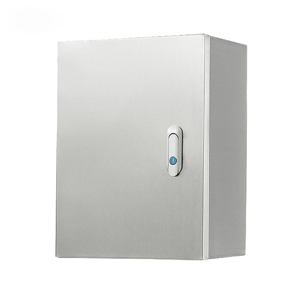
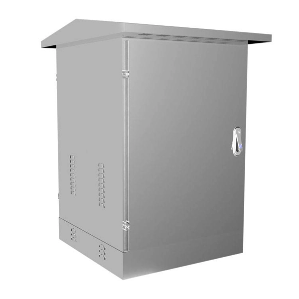
Connect the input and output wires to the corresponding terminals of the distribution box. This step is very crucial and can not bear any faults!. In this video, we'll walk you through the process of wiring a home distribution box with a detailed connection diagram. more Welcome to our channel! In this video. Before installation, it's important to know what makes up a distribution box. Let's break it down into two main parts: the outer shell and the electrical parts inside. The enclosure protects the electrical components from water, dust, and damage. When choosing one, check the IP or NEMA rating. A. A neutral link is used to distribute a neutral supply to all the output loads. When single-pole MCBs are used for output loads, the neutral wire of the loads is connected to the neutral link. Follow this guide for a clear and safe connection process: Before starting, always ensure the main power is turned off to avoid electrical shock. It is usually equipped with circuit breakers, fuses, terminal connectors, and other components. It is mainly used to isolate fault circuits, prevent overload, and ensure the safe operation of. Connection method: Each switch takes a wire from the incoming point and connects it to the incoming end of the switch, or uses parallel connection to reduce the difficulty of wiring. Wiring Direction: Wiring between the main circuit breaker and each branch circuit breaker in the box generally.
[PDF]

This manual describes the protection, automation, control, and monitoring functions of the SIPROTEC 5 devices. In order to protect technical infrastructures, systems, machines and networks against cyber threats, it is necessary to implement – and continuously maintain – a holistic, state-of-the-art. Busbar Differential Protection Definition: Busbar differential protection is a scheme that quickly isolates faults by comparing currents entering and leaving the busbar using Kirchoff's current law. Current Differential Protection: This protection method connects CT secondaries in parallel and. A busbar protection is a protection to protect busbars at short-circuits and earth-faults. In the “childhood” of electricity no separate protection was used for the busbars. With increasing short-circuit power in the network. SIPROTEC 7SS60 7SS60 is a numerical differential current protection for busbars. It is suitable for all voltage levels and can be adapted to a large variety of busbar configurations. Busbar protection is critical for the safe and reliable operation of a power system. Related Article: Busbar Protection Like any other faults. Bus bar protection scheme shall be provided for 220KV system where the sub-station layout arrangement is with 3-bus system (Main 1, Main 2 & Transfer Bus) or two bus system with Main bus with bus section breaker & Transfer bus.
[PDF]