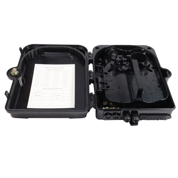
Learn how to splice fiber optic cable using fusion splicing with this complete step-by-step guide. Includes tools, best practices, loss standards (ITU-T G. 652), cost analysis, and FAQs for network engineers and installers. Splicing fiber optic cable is an extremely important phase for making dependable, high-speed communication infrastructures. Regardless of the type of fiber network you're deploying, be it for telecom, enterprise data centers, or smart city infrastructure, fusion splicing provides the benefits of. Proper connection of fiber optic cables is essential to harness these benefits fully, as even minor errors can lead to significant performance issues like signal loss. This article will guide you through the necessary tools, materials, and methods on how to connect fiber optic cables effectively. Previous video we explain how to do splicing of fibers optic cable in joint closure. this video are showing how to arrange sleeves in the cable tray and arrangement of fibers. Before connecting any fiber cable, you need to assemble the proper preparation tools: With the right tools in hand, follow these key steps to achieve reliable fiber connections: 1. Strip and Clean Fiber Ends. Fiber optic internet delivers blazing-fast speeds and reliable connectivity, making it a top choice for modern homes and businesses. However, setting up a fiber optic connection to your router can seem daunting if you're unfamiliar with the process.
[PDF]

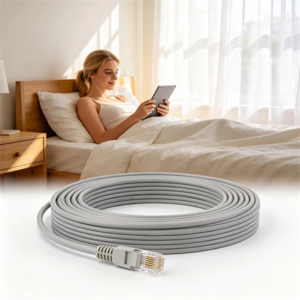
The video recommends using a pre-terminated fiber optic assembly and a pair of media converters for situations where your network connection needs to extend beyond 250 feet. You may look to extend your network for either a commercial or residential setting. Yes, fibre optic cables can be extended by using splice closures or optical connectors to join multiple cables together. This allows for longer distances to be covered without loss of signal quality. Yes, it is possible to extend fiber optic cable using various methods and techniques. Fiber optic. Proper connection of fiber optic cables is essential to harness these benefits fully, as even minor errors can lead to significant performance issues like signal loss. This article will guide you through the necessary tools, materials, and methods on how to connect fiber optic cables effectively. This blog post explains how to extend your network over long distances, exceeding the limitations of copper cabling, using fiber optics. This blog post looks at the various options available to installers for responding to these issues; from splicing and field-fit connectors to factory-terminated or pre-connectorization. For network managers and technicians, a poor splice can lead to significant signal degradation, network downtime, and costly troubleshooting. The goal is to align the ends of.
[PDF]
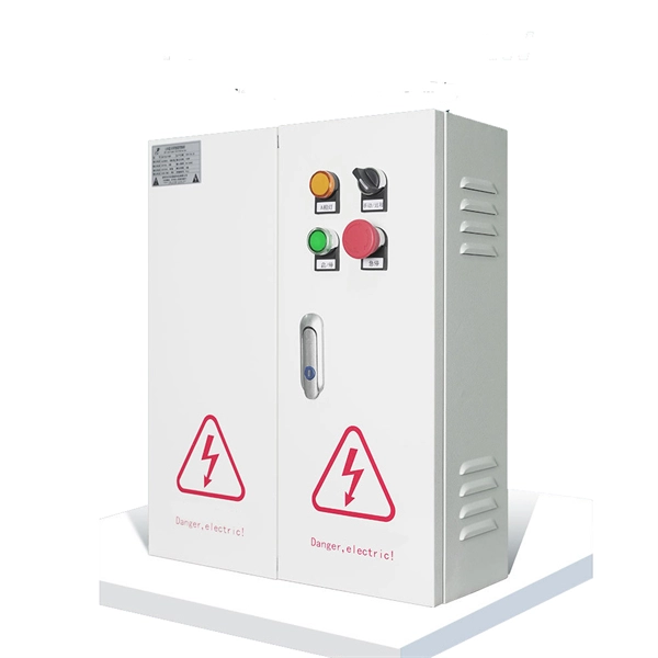
In this tutorial, you will learn the wiring of Change Over Switch, Voltage Protector, Main Breaker, and Room Breakers in a simple and professional way. Whether you are a beginner or an electrician, this DB wiring guide will help you understand the complete distribution board . Design requirements for low voltage distribution boxes cover NEC, IEC, and safety standards to ensure reliable, compliant electrical installations. You must make safety your top priority when working with low voltage distribution boxes. Design requirements help you follow important standards like. In this guide, we'll break down everything you need to know to install a distribution box correctly and confidently. Choose the right box based on environment (indoor/outdoor), load capacity, and durability. Check for proper IP/NEMA ratings and material quality. Just like travelers need clear pathways and safety protocols, your electrical circuits need proper management to prevent chaos. The National Electrical Code (NEC) requirements might seem like bureaucratic. A cable distribution box is an electrical device used to collect, distribute, and protect electrical power. It is usually equipped with circuit breakers, fuses, terminal connectors, and other components. In this. This prevents dangerous voltage differences between surfaces. System grounding establishes voltage reference points. Ground fault protection detects insulation failures quickly.
[PDF]
Learn how to connect your ONT, configure your router, and optimize Wi-Fi for fast, stable fiber internet at home or office. To set up your router for fiber internet quickly, connect the router to your fiber modem, access the router's settings via a web browser, and input the provided ISP credentials. Make sure to update the firmware, configure Wi-Fi security, and customize your network name for optimal performance. With. However, setting up a fiber optic connection to your router can seem daunting if you're unfamiliar with the process. In this guide, we'll walk you through how to connect a fiber optic cable to a router safely and efficiently. Why Use Fiber Optic Internet? Before diving into the setup, let's quickly. Setting up a fiber internet connection requires understanding key hardware components and following a specific connection sequence to establish your home network.
[PDF]
Connect the input and output wires to the corresponding terminals of the distribution box. Then press the wire onto the terminal with a wire stripper, or tighten the wire with screws. This step is very crucial and can not bear any faults!. This guide provides step-by-step instructions for connecting a distribution box and highlights key factors to consider during installation. What Is a Distribution Box? A distribution box, also known as an electrical distribution board, is a critical component in electrical systems. Whether you're an electrician or a DIY enthusiast, this guide will help you understand the basics of home electrical distribution. Covers wiring, placement, standards, and expert tips for a compliant setup. It takes the incoming power and safely distributes it to different circuits throughout your building. It serves as a central hub for distributing electricity throughout a building, ensuring that power is delivered safely and efficiently to all the required locations.
[PDF]
Den här guiden går igenom allt du behöver känna till när du vill koppla din egen router till fiber, vilka alternativ som finns, vilka inställningar som krävs och hur du felsöker om något inte fungerar som det ska. However, setting up a fiber optic connection to your router can seem daunting if you're unfamiliar with the process. In this guide, we'll walk you through how to connect a fiber optic cable to a router safely and efficiently. Why Use Fiber Optic Internet? Before diving into the setup, let's quickly. Setting up a fiber internet connection requires understanding key hardware components and following a specific connection sequence to establish your home network. This comprehensive guide combines industry standards with field-tested practices to ensure you achieve a rock-solid.
[PDF]

The simplest way to do it is with a fiber media converter on either side. In its basic form, this uses electricity to convert a single Ethernet twisted-pair copper connection to fiber, and back. Running fiber internally involves extending this high-speed link from the service entry point to a centralized location, such as a dedicated media closet or network rack. This DIY effort is undertaken to maximize performance, improve aesthetics, or relocate the Optical Network Terminal (ONT) to a. Proper connection of fiber optic cables is essential to harness these benefits fully, as even minor errors can lead to significant performance issues like signal loss. This article will guide you through the necessary tools, materials, and methods on how to connect fiber optic cables effectively. The process to connect fiber optic cable to router requires careful attention to detail, but I'll walk you through every critical step with the precision and clarity you deserve. In this guide, we'll walk you through how to connect a fiber optic cable to a router safely and efficiently. Why Use Fiber Optic Internet? Before diving into the setup, let's quickly. If you want to run fiber between the two buildings, you can do it on the LAN side of your router for fairly cheap. Instead of waiting for an appointment with a technician or trying to find a time that suits, you can have everything you need for a fast fiber connection shipped to your door, so you can set it up in your own time.
[PDF]
Step1 : Identify the optical cabinet and network operating center, and find the fiber optic splitter. Step 5: Patching from the splitter port to the user. Fiber optic patch cords must be installed correctly to ensure best network performance, reduce signal loss, and protect the sensitive fibers. Whether you're connecting a data center, a corporate network, or a high-density fiber infrastructure, correct installation methods are essential. Yingda. You can put in a fibre patch cord at home. You just need to follow easy steps and be careful. Planning helps you pick the right cord for your network. Be gentle when you handle the cord. Fibre patch cords last longer and are tougher than. This article will guide you through the necessary tools, materials, and methods on how to connect fiber optic cables effectively, ensuring you achieve optimal performance from your fiber optic network. Have a network installation project? Fiber Optic Cables: The primary medium for your connections. NS Comm provides enterprise-grade fiber optic patch cables engineered for maximum reliability and low-loss performance. However, proper installation techniques are essential to unlock their full potential. This guide will help you understand fiber construction, installation steps, real attenuation. Correct patch-cord installation is essential for maintaining low insertion loss, stable return loss, and long-term reliability in both indoor and outdoor fiber networks.
[PDF]

This manual describes the protection, automation, control, and monitoring functions of the SIPROTEC 5 devices. In order to protect technical infrastructures, systems, machines and networks against cyber threats, it is necessary to implement – and continuously maintain – a holistic, state-of-the-art. Busbar Differential Protection Definition: Busbar differential protection is a scheme that quickly isolates faults by comparing currents entering and leaving the busbar using Kirchoff's current law. Current Differential Protection: This protection method connects CT secondaries in parallel and. A busbar protection is a protection to protect busbars at short-circuits and earth-faults. In the “childhood” of electricity no separate protection was used for the busbars. With increasing short-circuit power in the network. SIPROTEC 7SS60 7SS60 is a numerical differential current protection for busbars. It is suitable for all voltage levels and can be adapted to a large variety of busbar configurations. Busbar protection is critical for the safe and reliable operation of a power system. Related Article: Busbar Protection Like any other faults. Bus bar protection scheme shall be provided for 220KV system where the sub-station layout arrangement is with 3-bus system (Main 1, Main 2 & Transfer Bus) or two bus system with Main bus with bus section breaker & Transfer bus.
[PDF]

In this step-by-step guide, we will walk you through the process, ensuring that you can seamlessly connect your optical cable and enjoy a clear and uninterrupted audiovisual experience. Optical cables are becoming increasingly popular for transmitting high-quality. Optical audio cables can easily improve your TV's sound by connecting to external speakers. Learning how to connect an optical cable is easy, but there are a couple of gotchas that you should know. Here are the basics: Identify the optical output; if there's a protective plastic cap, remove it. The most common types are: The Toslink optical cable is a standard for transmitting digital audio signals. It uses a plastic or glass fiber to carry light signals from one. You can connect an older flat screen TV to ANY Stereo system, Surround Sound system, or Soundbar. This video shows you step by step how to make audio connections using an digital optical cable. You can use an optical connection even if your audio system does not have an optical socket, and by using. One of the easiest ways to achieve high-quality sound is to connect your TV to a home theater system or soundbar. Easily connect your optical audio cable to your TV! Follow our step-by-step guide for a hassle-free setup and enjoy crystal-clear sound. No wonder how to improve TV sound, right? When the sound is weak, for example, when using an analog sound source, then an optical audio cable possibly will be the.
[PDF]

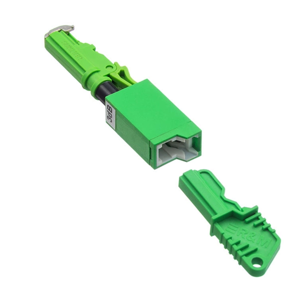
NOTE: Insert the end of a colored wire into one of the holes in a butt connector. With the wires pushed tightly against the far inside wall of the connector, squeeze the red button until it depresses. The OS-8171 Beam Splitter is designed to be used with the OS-8170 Brewster's Angle Accessory and the OS-8539 Educational Spectrophotometer System. ) In the Brewster's Angle experiment, the Beam Splitter is used with a. am Splitters/Combiners. This document describes this product line, as well as general operation guidel into two output beams t beams of equal power. The standard product is designed for use in the visible spectrum 400-700 nm wavelength). Custom Surgical Beam Splitter sends 50% of the light to the eyepieces and 50% to the smartphone camera. If you want to understand more about how beam splitter works, watch the video below. It is not necessary to. As title. in your towing vehicle manual. Be sure the hitch is installed onto the vehicle. Releasing the pin before will cause supp owards the engine faster than you can let go. This is because if a fire. Meadowlark Optics presents its VersalightTM wire grid polarizing beam splitters. Manufactured for wavelength ranges between 420 and 2600 nm, this polarizer is ideal for broadband and wide field-of-view applications. Wire grid polarizing beam splitters are manufactured out of our Versalight wire.
[PDF]

In this video, we'll show you how to connect an energy meter to a distribution board (DB) safely and efficiently. energy meter connection with distribution box How to Connect an Energy Meter to Your Distribution Box Easily Steps to Properly Connect Your Energy Meter to a Distribution Box. It plays a vital role in ensuring the safe and efficient distribution of electricity throughout the premises. What is the wire from the meter to the breaker box? Also. Always begin with disconnecting the main supply before accessing any enclosure containing distribution components. This prevents arc faults and ensures safety when modifying or inspecting current paths. This “meter to panel” wiring establishes the pathway for all incoming electrical power from the grid to the home. Its primary function is to safely and reliably. Distribution Board aslo know as “Panel Board”, “Switch & Fuse Board” or “Consumer Unit” is a box installed in the building containing on protective devices, such as circuit breaker, fuses, isolator, switches, RCDs and MCBs etc. The electric main supply (230V AC & 120V AC in US) is connected through. Changed Texas's reference diagram for the 3 wire network 120/208 Volt single phase self-contained Revised Figures 13, 14, 14b. Limited the meter location from pad mount transformer for PSO. Removed unistrut being listed as an alternative means for mounting the meter box. APCo and TX do not allow.
[PDF]

Connect the input and output wires to the corresponding terminals of the distribution box. This step is very crucial and can not bear any faults!. In this video, we'll walk you through the process of wiring a home distribution box with a detailed connection diagram. more Welcome to our channel! In this video. Before installation, it's important to know what makes up a distribution box. Let's break it down into two main parts: the outer shell and the electrical parts inside. The enclosure protects the electrical components from water, dust, and damage. When choosing one, check the IP or NEMA rating. A. A neutral link is used to distribute a neutral supply to all the output loads. When single-pole MCBs are used for output loads, the neutral wire of the loads is connected to the neutral link. Follow this guide for a clear and safe connection process: Before starting, always ensure the main power is turned off to avoid electrical shock. It is usually equipped with circuit breakers, fuses, terminal connectors, and other components. It is mainly used to isolate fault circuits, prevent overload, and ensure the safe operation of. Connection method: Each switch takes a wire from the incoming point and connects it to the incoming end of the switch, or uses parallel connection to reduce the difficulty of wiring. Wiring Direction: Wiring between the main circuit breaker and each branch circuit breaker in the box generally.
[PDF]

This comprehensive guide will explore the importance and benefits of this integration, provide an understanding of fiber optic cable and Ethernet ports, discuss their compatibility, and offer a step-by-step process for connecting them. Proper connection of fiber optic cables is essential to harness these benefits fully, as even minor errors can lead to significant performance issues like signal loss. This article will guide you through the necessary tools, materials, and methods on how to connect fiber optic cables effectively. Using an optical cable involves connecting it to the right equipment, ensuring proper installation, and testing the system for optimal performance. Here's a step-by-step guide on how to use optical cable effectively: 1. Check Compatibility of Equipment Ensure that your equipment (e., network. One powerful solution to achieve these goals is by connecting fiber optic cables with Ethernet ports. This comprehensive guide combines industry standards with field-tested practices to ensure you achieve a rock-solid. These transceiver modules are hot-swappable input/output (I/O) devices that plug into 100BASE, 1000BASE and 10GBASE ports (for SFP+), which connect the module port with the fiber-optic or copper network. The SFP transceiver modules are hot-pluggable I/O devices that plug into module sockets. The number one cause of signal loss in optical fiber installations is dirt on.
[PDF]

In a metal box, a wire type equipment grounding conductor can be attached to the box with a ground screw or clip and terminated to the switch or receptacle in the box. Connecting the receptacle grounding terminal to the metal box ensures an effective ground-fault current path. The basic rule achieves this through an equipment grounding jumper; four exceptions. A main bonding jumper is required to bond the service disconnect enclosure to the service neutral conductor [250. Not all boxes are metal or provide. The main bonding jumper bonds the neutral conductor to the equipment grounding conductor, enabling proper operation of overcurrent protective devices. Neutral conductors must be properly sized based on the load and installation method, with specific requirements for conductors in parallel or. According to the National Electrical Code (NEC), this connection is made between the grounded conductor (typically the neutral) and the equipment grounding conductor (EGC) system at the service equipment. Proper location and sizing are not just best practices; they are essential for ensuring that. NEC Article 250 is dedicated entirely to grounding and bonding, outlining the specific conductors and connections required. Grounding Electrode Conductor (GEC): This is the wire that connects the grounding electrode (the rod) to the grounding bus bar in the main electrical panel.
[PDF]