
In this guide, I'll walk you through everything you need to know about choosing the right cable trays for your cables. Whether you're dealing with power cables, control cables, or communication cables, I'll break it down step by step. A 50 mm cable tray is used to organize and protect cable routes in industrial, commercial, and infrastructure facilities. This compact solution is suitable for power distribution lines, low-current systems, and engineering communications. Mirankul Group manufactures cable trays in Uzbekistan. Accessories for cable systems include a variety of different components necessary for the proper functioning of cable routes. They provide a structured and secure pathway for cables, ensuring organized installation and easy maintenance. Cable Trays are important for ensuring the protection of the wiring system and supporting insulated electric cables used for distribution and communication. Brilltech Engineers Pvt. Understand Your Cable Tray Requirements Before selecting a cable tray, consider the following key factors:. Selecting cable trays can feel overwhelming, especially with so many options available. But don't worry—I've got you covered.
[PDF]

This article helps network engineers, field techs, and IT managers choose the right single-mode transceiver campus optics by tying IEEE Ethernet requirements to day-to-day deployment constraints: reach, budgets, DOM behavior, and operational limits. Huawei eKit offers a comprehensive series of pluggable optical modules in the Huawei eKit portfolio. The wide variety of modules gives you flexible and plug-and-play options for all types of interfaces. You will also get a practical checklist, common. Multimode and Singlemode optical modules differ in terms of fiber type, transmission distance, cost, and application scenarios. Understanding these differences is the first step in selecting the right module. This saves space and money. Dual fiber modules use two fibers. They are easier to set up and give steady communication. Its primary function entails converting electrical signals into optical signals. This assembly comprises a light source, such as a laser diode or a semiconductor light-emitting diode (LED), an optical interface, a. A single-mode receiver is an optical device that converts incoming light signals—carried over single-mode fiber (SMF)—back into electrical data. Unlike multimode receivers, which accept wider light beams from LEDs or VCSELs, single-mode receivers pair exclusively with laser-based transmitters.
[PDF]

In this post, we'll walk you through practical tips, essential tools, common pitfalls, and the techniques that will help you get your fibre patch cable installations right the first time. Correct patch-cord installation is essential for maintaining low insertion loss, stable return loss, and long-term reliability in both indoor and outdoor fiber networks. Proper handling, routing, cleaning, bend-radius management, and connector alignment ensure that the optical link meets design. Proper connection of fiber optic cables is essential to harness these benefits fully, as even minor errors can lead to significant performance issues like signal loss. This guide addresses expert-certified best practices applied by professionals in the telecommunications, data. Yingda outlines the tools and materials needed to install fiber optic patch cords, as well as a complete step-by-step installation guide and important safety considerations to take. We will also tie this procedure back to the earlier discussion of multi-mode fiber types (OM1 to OM5) and connection. The Flex-Angle boot is designed to bend any angle or direction from straight to 90°. OMC flex angle boots for LC&SC fiber optic connectors are available on any single-mode or multimode patch cord. They are designed so the installer can pre-bend the boot into any direction or angle. Selecting the correct fibre patch lead is crucial for optimising signal performance and.
[PDF]

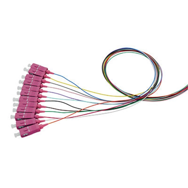
Here's what to consider: 1. Fiber Type Choose single-mode for long-distance transmission and multimode for shorter runs. Connector Compatibility Match the connector (LC, SC, ST, etc. ) with your equipment ports. Fiber Count Select based on network scale—higher. Executive Summary: A fiber optic pigtail is one of the most commonly specified yet least understood components in structured cabling. Get the wrong connector type, the wrong polish, or skip proper fusion splicing technique—and you're looking at elevated signal loss, increased back reflection, and a. Today, I'll show you how to pick the right patch cord or pigtail — step by step. You plug it into a switch, router, or patch panel. A pigtail is for splicing. You fuse it to a. A fiber pigtail is a single, short, usually tight-buffered fiber optic cable with a factory-installed connector on one end, and un-terminated fiber on the other end. Fiber optic pigtails are used to terminated fiber optic cables via fusion splicing or mechanical splicing as shown in the picture. In this guide, we'll break down what fiber optic pigtails are, how they work, their types, and how to choose the right one for your application. By the end, you will have a comprehensive understanding of why pigtails deserve a place in every fiber deployment toolkit. Each type has its own unique design, size, and compatibility features. Understanding these differences is essential for choosing the right pigtail for your network.
[PDF]

In the 2020 NEC ®, no more than 18 inches of cable length is allowed between the cable entry to the box and the closest cable support (see image). Below is a preview of the NEC®. ORG for the complete code section. The previous code language could technically allow an unlimited length of coiled up NM cable inside the wall as long as it was secured within 12 inches of the box. This code is based upon the type of box, wires, wire sizes, wire clamps and conduit fittings. Adjustments are made for the ground wire as you will see in the. Calculate and select the right number and spacing of cables for junction boxes using NEC guidelines to ensure safe, code-compliant electrical installations. This step keeps your project safe and. According to the National Electrical Code (NEC), the conductor must be long enough to extend outside the box's opening. This length allows enough room to connect, splice, or terminate wires without strain or damage. If wires are too short, they may fail inspection or create hazards during. The length of wire left inside an electrical box is a matter of strict compliance, safety, and functionality. Having the correct amount of slack ensures that future maintenance, repairs, or device replacements can be performed without difficulty. Proper electrical box fill calculations are critical for code compliance and safety in both residential and commercial installations.
[PDF]

Average Optical Power: How bright the light is (measured in dBm). Too dim? Your signal gets lost in the fiber. Extinction Ratio: The difference between “on” (1) and “off” (0) light power. A higher ratio = cleaner signals. Transmitter Side: An electrical signal hits a laser diode (LD) or LED, which spits out light. Receiver Side: Light enters a photodetector (like a tiny solar cell), which turns it back into electricity. A built-in amplifier boosts the signal for your. The average transmitted optical power refers to the optical power output by the light source at the transmitting end of the optical module under normal working conditions, which can be understood as the intensity of light. In communication, we usually use dBm to represent optical power. However, in practical use, we adopt the average Tx power. The transmission power is related to the. This article provides an in-depth analysis of two key performance indicators of optical modules: transmitter power and receiver sensitivity. Transmitter power characterizes the average optical power output from the laser under rated conditions, while receiver sensitivity indicates the minimum. An optical module is a connecting module that serves as an optical-electrical conversion device. At the receiver end, the optical signals are reconverted into electrical.
[PDF]

This blog explains how to use Kubernetes resource quotas for efficient resource management. It covers key concepts, step-by-step implementation, YAML examples for Pods, PVCs, ConfigMaps, and tips for monitoring, troubleshooting, and optimizing quotas. On the Quota Management node of the File Server Resource Manager Microsoft ® Management Console (MMC) snap-in, you can perform the following tasks: Create quotas to limit the space allowed for a volume or folder, and generate notifications when the quota limits are approached or exceeded. Generate. Service Quotas is a service for viewing and managing your quotas easily and at scale as your AWS workloads grow. Quotas, also referred to as limits, are the maximum number of resources that you can create in an AWS account. What Are Resource Quotas in. Resource quotas are a tool for administrators to address this concern. A resource quota, defined by a ResourceQuota object, provides constraints that limit aggregate resource consumption per namespace. A ResourceQuota can also limit the quantity of objects that can be created in a namespace by API. Disk quotas allow Windows administrators to control and limit the amount of disk space that users use on the file systems of servers and workstations. Windows Server supports two types of disk quotas: File Server Resource Manager quotas and NTFS quotas.
[PDF]

Download a comprehensive set of Cable Tray Installation CAD Blocks in DWG format, ideal for electrical engineers, MEP designers, and industrial layout planners. Electrical cable tray layout is a ready-to-use CAD block perfect for building services, industrial setups, and electrical projects. This cable tray CAD block is compatible with AutoCAD and other DWG-supported software, allowing precise placement and easy integration into your designs. Save time and. Discover all CAD files of the "Cable trays" category from Supplier-Certified Catalogs ✅ SOLIDWORKS, Inventor, Creo, CATIA, Solid Edge, autoCAD, Revit and many more CAD software but also as STEP, STL, IGES, STL, DWG, DXF and more neutral CAD formats. This collection includes installation details for ladder trays, perforated trays, solid-bottom trays, and wire mesh trays, along with. Tray installation details for the location of a project's electrical wiring; in addition to blocks with different angles that allow the wiring circulation to be identified. Download this FREE 2D CAD drawing of CABLE TRAYS including various widths. This autocad drawing can be used in your mechanical design CAD drawings. dwg format) Our CAD drawings are purged to keep the files. Already Subscribed? Download free cable trays in DWG or CAD block format. Cable tray details.
[PDF]

Dispersion of an optical fiber directly affects the bandwidth and distance capability of the fiber optic link and reduces its efficiency. The higher the dispersion, the lower the potential data rate and transmission distance. Fiber optic cable transmission distance is determined by two primary physical factors that affect signal quality as light travels through the fiber medium. The greater the distance, the greater. With amplifiers, such as Erbium-doped fiber amplifiers (EDFAs), the distance can be extended to 600 miles or more, and even further with additional amplifiers for long-haul applications. In this guide, we'll explore how fiber optic cables function, the maximum distances for different types of fiber optics, and tips for. Fiber optics transmits information by sending light signals through thin strands of glass. While this technology offers higher speeds and longer distances than traditional copper wiring, physical limitations impose distance constraints. Light pulses degrade as they travel over long spans, primarily. The maximum distance a fiber optic cable can transmit data reliably is influenced by several key factors, primarily the inherent properties of light and the physical characteristics of the fiber itself. Understanding these limitations is essential for designing efficient and robust internet.
[PDF]

In this tutorial, we will show you how to fusion splice two fiber optic strands together in an easy 12 step process. The answer lies in splicing, both fusion and mechanical. Whether you're a professional technician or a DIY enthusiast, understanding the process of fusion splicing fiber optic cables is essential for maintaining high-speed communication networks. - Fiber Instrument Sales What is Fusion Splicing? How fiber optic splicers work, types, what they are used for. Steps to use this equipment and including how to test your fiber splice. The guide covers everything from basic principles of fusion splicing to detailed procedures; it is intended to provide both newbies and professionals with the necessary knowledge and skills. The operation and skills of fiber optic fusion splicing technology can be mainly divided into five steps: fiber stripping, fiber cutting, fiber melting, fiber sleeve, and fiber winding. And tools used for fiber fusion: fusion splicer; fiber cleaver; cable stripper; fiber optic stripper; alcohol;.
[PDF]
In this guide, I'm excited to share with you 15 creative and surprisingly simple ways to transform your ugly electrical box from an eyesore into a part of your home you might actually want to show off. There are actually a whole host of creative and, more importantly, stylish ways to conceal your breaker box or electrical panel without blocking access or impeding functionality. But before you get started, make sure you double-check with an electrician and your local codes. Some electrical codes. Either way, here are unique electrical panel cover ideas to give you some inspiration. Don't let an ugly gray metal electrical panel ruin your decor! Check out these creative solutions for covering one in any room (removable, of course). Our editors and experts handpick every product we feature. We may earn a commission from your purchases. Which is exactly where I was struggling, we have an electrical panel directly in our dining room (small space problems). These fellow bloggers turned their electric panel doors from eyesores into focal points and pieces of art.
[PDF]

If you are ever in need of checking your ONT, this video will show you how to do so and what it is you are looking for. Always remember to securely close the box afterwards to prevent any damage to the facilities inside. more. A fiber termination box is the standard instrument used in fiber optic networks to connect, secure, and protect optical fibers at the terminating point. It functions as a junction between the incoming fiber cable and the outgoing customer-side fiber cable, where one fiber can be spliced, patched. Open the Fiber optic terminal box. Check and prepare installation tools and accessories. Prepare the cable according to the design. An ONT, or Optical Network Terminal, is the box where your fiber internet connection enters your home to power your fiber network. Your ONT is typically located in your garage, basement or outside your home within a few feet of your home's power box. It serves as a termination point for optical fibers, providing a secure and organized space for connecting and managing fiber optic cables. A fiber pigtail is a specific hardware connection used for cable termination. Proper installation and maintenance of FTBs are essential to ensure the reliability and performance of the network infrastructure.
[PDF]

The first thing you should do is locate the fiber optic cable that comes from the service provider. Once inserted, make sure it is securely. However, setting up a fiber optic connection to your router can seem daunting if you're unfamiliar with the process. Why Use Fiber Optic Internet? Before diving into the setup, let's quickly. Ensure your fiber optic router has an available WAN (Wide Area Network) or Ethernet port for the fiber optic modem. It's thin, flexible, and usually comes with connectors on both ends. Power Cables: Get power cables for both the. The fiber optic cable does not plug directly into a standard home router because the signal type must be translated. The fiber line terminates at the Optical Network Terminal (ONT), which is typically supplied and installed by the internet service provider. This specialized equipment serves as the. The process to connect fiber optic cable to router requires careful attention to detail, but I'll walk you through every critical step with the precision and clarity you deserve. Here's a step-by-step guide to help you through it. Understand the Basics Before diving in, familiarize yourself with the components involved:. Follow along as we take you through the step-by-step process of installing fiber internet! From preparing the site to connecting the final cables, we'll show you what goes into bringing high-speed internet to your doorstep. Whether you're a tech enthusiast or just curious about how it all w.
[PDF]

Excavate the cable at the break point and use a fiber optic cutter to remove the damaged section. Use a high-precision fiber cleaver to prepare the fiber ends for splicing. Step1 : Identify the optical cabinet and network operating center, and find the fiber optic splitter. Step 2: Identify the splitter number. Step 4: Find the optical fiber port and cable sequence that leads to the user. 2) The. Here are the steps to patch a fiber cable. Make sure the connectors are free from dust or dirt and that there is no damage to the cable's. When fiber cables sustain damage, specialized repair techniques help restore connectivity and maintain data integrity. This comprehensive guide outlines professional fiber optic repair protocols that align with industry best practices. Adhering to precise methodologies, we can mend impaired cables. Learn how to splice fiber optic cable step by step in this complete guide! In this video, you'll see the full fiber splicing process — from fiber preparation, cleaving, and fusion splicing to final testing. Whether you're a network technician, IT professional, or telecom operator, you'll find practical steps, tools, and tips to restore. By understanding these key elements and following the outlined steps, you can effectively repair fiber optic cables and maintain the high-performance network necessary for today's demanding communication needs. When it comes to ensuring nice network experiences for users, the condition of a fiber.
[PDF]

In this tutorial, I will show you how you can connect the Optocoupler to Arduino, read the data as Analog or Digital, and if necessary convert the analog values to digital, and how to reduce noise from the sensor. The Infrared Slotted Optical Optocoupler Module is a device that uses infrared light to transmit signals between two electrically isolated circuits. It consists of an infrared emitter (LED) and a photodetector (phototransistor) housed in a slotted enclosure. When an object passes through the slot. Slotted Optocouplers (Photo Interrupters) are very useful sensors, often included in Arduino projects to detect position of moving objects, measure speed of rotation, or linear motion, frequency of events, and many others. They are easy to use, but it is important to understand how they work, so. This tutorial is a comprehensive, practical guide to the Speed Sensor / Tacho Sensor (Slot-Type Optocoupler) (Leobot Product #245). Moreover, a simple application is programmed that shows how to wire and how to program an Arduino when working with the module. In this tutorial, the module is used as an “digital input board”. If you want to use the. In this project, I will talk about Phototransistor Optical Interrupter Switches (Opto Coupler) Module, how this module works and helps in determining the speed of a rotating object and finally I will show you how to Interface Optical Interrupter Switch Sensor with Arduino and measure the speed of a.
[PDF]