Due to power demands, there are currently no pluggable 10GBase-T or NBase-T SFP modules; all of the current products on the market are fixed interfaces only. 10GBase-SR is the original multimode optics specification and is still by far the most commonly used. A 10GB SFP module, more accurately referred to as a 10G SFP+ (Small Form-Factor Pluggable Plus) transceiver, is a hot-pluggable network interface module designed to transmit and receive data at speeds of up to 10 gigabits per second. It serves as the physical-layer connection between network. A broad range of industry-compliant SFP+ modules for 10 Gigabit Ethernet deployments in diverse networking environments. The Cisco ® 10GBASE SFP+ modules (Figure 1) give you a wide variety of 10 Gigabit Ethernet connectivity options for data center, enterprise wiring closet, and service provider. FS 10GbE SFP+ module solutions provide a wide variety of 10 Gigabit Ethernet connectivity options for data centers, enterprise wiring closets, Internet Service Providers (ISPs) applications. Click to get your 10G SFP+ transceiver modules from nearby warehouses. Trusted by 260K+. Single-fiber bidirectional (BIDI) optical modules must be used in pairs. For example, SFP-10G-BXD1 must be used with SFP-10G-BXU1. As it uses a single, low-cost. Our Cisco, HP and Brocade ready 10GBASE-SR Multimode SFP+ Modules feature low power consumption (<800mw) using Duplex LC OM3 fiber up to 300m (984').
[PDF]

This is a simple video showing how to install a 850nm fiber optic link using SFP transceivers between 2 10 Gigabit backbone switches. Covers transceiver inst. As a leading provider of fiber optic solutions, Weunion offers a wide range of SFP-compatible products, including optical transceivers, DAC/AOC cables, LC patch cords, and MPO/MTP assemblies. This guide explores the essentials of SFP connectivity, installation best practices, and how Weunion's. These transceiver modules are hot-swappable input/output (I/O) devices that plug into 100BASE, 1000BASE and 10GBASE ports (for SFP+), which connect the module port with the fiber-optic or copper network. This document contains these sections: The SFP transceiver modules are hot-pluggable I/O. An optical module is an optoelectronic conversion device that transmits data by converting electrical signals into optical signals. Common types of optical modules include SFP, SFP+, SFP28, QSFP, QSFP28, etc. Different types of optical modules have different performance parameters such as speed. The 1310 nm WWDM solution, 10GBASE-LX4, requires the use of a mode-conditioning patch cord on multimode fiber to achieve its specified range of operating distances. more Audio tracks for some languages were automatically generated. Learn more This is a simple. One of the most widely deployed optical solutions for short-distance 10G links is the multimode SFP+ transceiver, commonly referred to as a 10GBASE-SR module.
[PDF]
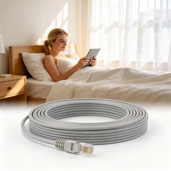
Fiber optic cable installation costs between $1,500 and $7,000 for your home, with prices varying by cable length and installation method. The installation type you choose and the layout of your property determine the total labor and materials needed for your project. How Much Does Fiber Optic Installation Cost Per Foot? Cable Material Costs: Installation Costs by Method: Prices can range from $1 to $50+ per linear foot depending on the method and complexity. The initial cost of installing fiber optic cables can vary depending on the chosen installation method. Home and business fiber optics projects typically range from a few hundred to several thousand dollars, depending on run length, fiber type, and labor needs. This. Whether you're running fiber to a home or a data center, here's exactly what contractors are charging in 2026. What is the real cost of fiber optic cable per foot in 2026? After analyzing 40+ U. fiber projects, we've assembled current material rates, labor burdens, and hidden fees. You should account for permit. If you're grappling with the complexities of budgeting for fiber optic installations 1, understanding the cost dynamics of single-mode fiber optic cables 2 is crucial. The price per foot includes the fiber itself, connectors, and basic installation factors, with main drivers being cable type, distance, and any required conduit or termination hardware. This article outlines cost expectations.
[PDF]

Arduino Safety Relay Box With Wall Socket : A relay is an electrically operated switch. In this project there is no real need to isolate one circuit. Relay rooms are essential in modern commercial or industrial buildings, serving as secure enclosures for electrical relays that manage power distribution and automation systems. Designing a relay room requires balancing technical precision with safety, efficiency, and future scalability. Many relays use an electromagnet to mechanically operate the switch and provide electrical isolation between two circuits. In this article, you will learn how to design an electrical control cabinet for optimal safety and efficiency, following some. This handbook covers the code of practice in protection circuitry including standard lead and device numbers, mode of connections at terminal strips, colour codes in multicore cables, dos and donts in execution. Reliable components ensure system faultlessness and durability. Modern design and user-friendliness. equipment of most. This is Part 1 in a series of tutorials that will show you how to build a Bussmann RTMR fuse/relay block. If you're not familiar with this product, it's a simple waterproof enclosure that allows you to connect accessories on your vehicle through relays and/or fuses. After reading this tutorial, you.
[PDF]
Step1 : Identify the optical cabinet and network operating center, and find the fiber optic splitter. Step 5: Patching from the splitter port to the user. Fiber optic patch cords must be installed correctly to ensure best network performance, reduce signal loss, and protect the sensitive fibers. Whether you're connecting a data center, a corporate network, or a high-density fiber infrastructure, correct installation methods are essential. Yingda. You can put in a fibre patch cord at home. You just need to follow easy steps and be careful. Planning helps you pick the right cord for your network. Be gentle when you handle the cord. Fibre patch cords last longer and are tougher than. This article will guide you through the necessary tools, materials, and methods on how to connect fiber optic cables effectively, ensuring you achieve optimal performance from your fiber optic network. Have a network installation project? Fiber Optic Cables: The primary medium for your connections. NS Comm provides enterprise-grade fiber optic patch cables engineered for maximum reliability and low-loss performance. However, proper installation techniques are essential to unlock their full potential. This guide will help you understand fiber construction, installation steps, real attenuation. Correct patch-cord installation is essential for maintaining low insertion loss, stable return loss, and long-term reliability in both indoor and outdoor fiber networks.
[PDF]
In order to achieve consistent and compatible fibre systems, it is recommended that the convention defined in ISO / IEC 11801 is used where channel A (right) is the input and channel B (left) is the output. Fiber optics relies on a bidirectional transmission where the transmitter port on one end connects to the receiver port on the other end. Since fiber optic links require a two-way - or duplex - connection, there is potential for errors in installation by connecting transmitter to transmitter or. Fiber polarity is the direction that light signals travel from one end of a fiber optic cable (link) to the other. Although it may seem obvious, fiber optic polarity is a frequent source of confusion and. Polarity in fiber optic networks refers to the alignment of transmit (Tx) and receive (Rx) signals between interconnected devices. This principle becomes more complex when dealing with multi-fiber MPO (Multi-Fiber Push-On) connectors, which typically house 12, 24, or even 48 fibers in a single. Because fiber systems are directional, maintaining polarity is crucial. It defines the direction that optical signals travel inside the fiber. Without polarity, data won't flow the way it needs to. Ensuring proper polarity means that “transmit” talks to “receive.
[PDF]

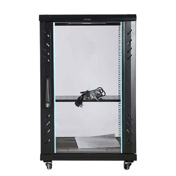
How to install a fiber optic cable into a patch panel. Fibre Optic Patch Panel Installation Fibre Optic Cabling Know How - how to connect Fibre Optic Cable to a Patch Panel This video shows you how to install. Fiber optic patch panel is a crucial component in optical communications networks. It also known as a fiber patch panel or fiber distribution panel. It serves as a central point for organizing, managing, and connecting fiber optic cables. At its core, a fiber optic patch panel acts as a hub for. What are the best practices for fiber patch panel installation? The best practices below help to avoid installation issues and ensure ease of service for the system. Penetrate the enclosure from the side or bottom to minimize the risk of water intrusion. Step 1: Gather the Tools and Equipment The first step in connecting. How to Install a Fibre Optic Cable into a Patch Panel ( Fibre Optic Patch Panel ) How to install a fiber optic cable into a patch panel. This is essential for streamlining network. Running fiber internally involves extending this high-speed link from the service entry point to a centralized location, such as a dedicated media closet or network rack. This DIY effort is undertaken to maximize performance, improve aesthetics, or relocate the Optical Network Terminal (ONT) to a.
[PDF]
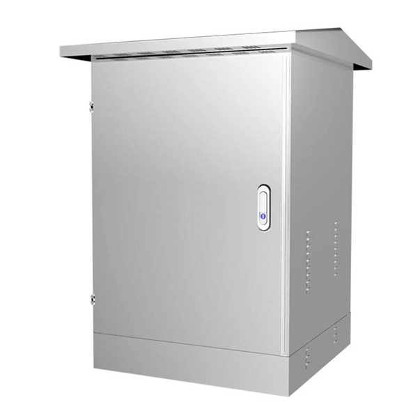
• The sliding door low profile aisle containment system shall create a structure including end of row doors and ceiling panels that enclose the cold aisle between rows of cabinets to segregate cold and hot air streams to and from equipment. •This passive system shall. We create purpose-built laboratory environments for educational and research institutions — combining enduring craftsmanship, thoughtful customization, and true project partnership. We engineer, manufacture, and deliver premium wood casework solutions for education, healthcare, and research. Our. uploading. This Product Category has products that are hidden either due to your Product Country of Use settings or your chosen filters. Maintain optimal temperature control in your data center while ensuring easy equipment access with. Cold aisle containment creates an enclosed corridor in front of server cabinets, ensuring that the coldest air goes directly into equipment intakes. By isolating the cold aisle, containment reduces unintended mixing of cold supply air with hot exhaust air, maintaining uniform, predictable. $1,230. 70Original price was: $1,230. ) Overall Height (In. ) • The sliding door low profile aisle containment.
[PDF]
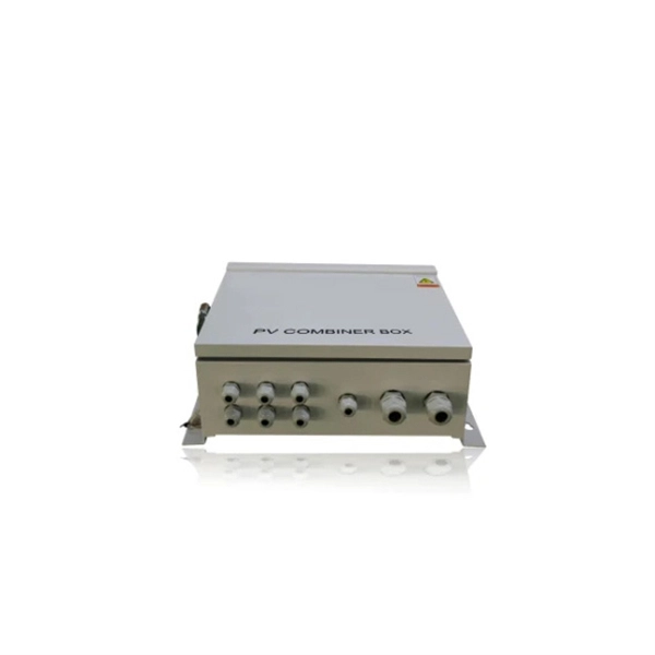
Attach a ground wire from one of the threaded studs (A) at the bottom of the housing, to the mounting plate (B). The ground resistance between all system parts shall be <. The protective grounding system, which includes conductor grounds and worker bonding, must be engineered to protect workers from hazardous voltages that can be created by line reenergizing, lightning, or induced oltage. If more than one crew is working independently on the same deenergized line or. Power from factory ground must be installed by a qualified electrician. Each DISTRIBUTION BOX and controller must be grounded. On the US market, a 5. 26 mm 2 (10 AWG) ground wire must be used, and in all other markets a 6 mm 2 must be used. The neutral conductor is typically the grounded conductor connected to the system's neutral point, carrying current under normal operation. Grounding electrode conductors must be connected at. The correct connection method of Distribution box grounding wire mainly includes the following steps: 1. Whether you're a seasoned pro or just starting out, this comprehensive guide will give you practical. This technical article covers protective grounding requirements for steel tower and wood pole supported transmission and distribution lines, and insulated power cables. Protective grounds must be installed so all phases of lines or cable are visibly and effectively bonded together in a multi-phase.
[PDF]

Start by examining the plastic cover closely to identify any tabs or locking mechanisms that may be holding it in place. This robust enclosure houses either the main service disconnect or a sub-panel, acting as a control point for electricity distribution to the property or a dedicated outdoor system like a pool or workshop. Gaining access to the panel's interior is usually necessary for simple tasks like resetting a. Opening electrical boxes outside can be a tricky endeavor. Without the proper tools, knowledge, and safety measures, it can also be dangerous. However, with a few simple steps, you can open an outdoor electrical box safely and efficiently. This is how you can open them to have access to the plug-ins. Once you've loosened the. This guide will explore the steps and considerations for safely and effectively punching out a plastic electrical box. Ensure the wires are not powered before starting work. Flat-head screwdriver, electrical pliers, hammer, and a suitable meter or tester. Locate. Before you attempt to open an outdoor breaker box, it's crucial to prioritize your safety. Here is a set of guidelines to ensure you undertake this task without any hazards: Confirm power is disconnected to the unit by turning off the main breaker or disconnecting the main fuse.
[PDF]

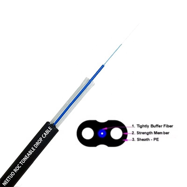
This visualization shows the growth of the undersea cable network, global internet peering capacity, and the distribution of IP addresses via BGP announcements over time. Use the controls at the top to play the animation or step through year by year. The Submarine Cable Map is a free and regularly updated resource from TeleGeography. TeleGeography's comprehensive and regularly updated interactive map of the world's major submarine cable systems and landing stations. For more details and insights, please read this. Dongguan TW-SCIE Co.,Ltd is a professional manufacturer of FTTH drop cable, indoor/ outdoor fiber optic cable and patch cord. Products are conform to ISO 9001 standard. Welcome to visit us: Krasnopresnenskaya Naberezhnaya, 14. Dongguan Guanhong Optical Cable Co., Ltd (referred as Fiberplan) is a high-tech enterprise integrating the research, manufacture and marketing. And we can produce customized products as customer's require. The facility commenced operations in 2003, and its purpose was publicly revealed by AT&T technician Mark Klein in 2006. Room 641A is located in the SBC Communications building at 611 Folsom Street, San Francisco, three floors of which were occupied by AT&T before SBC purchased AT&T.
[PDF]

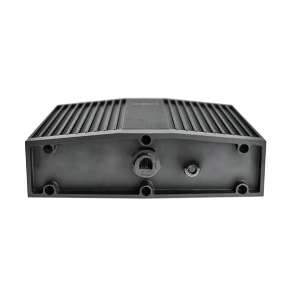
Arduino-Powered Data Transmission with Fiber Optics Welcome to our video tutorial on optical communication with Arduino, designed to be easy t. more. They consist of a transmitter on one end of a fiber and a receiver on the other end. Most systems use a "transceiver" which includes both transmission and. I'm going to use HFBR 1414 fiber optic transmitter module which is manufactured by Broadcom. It is a low-cost high-power transmitter that is designed for use in industrial power generation, power distribution, medical transportation and gaming applications. Internally, the optical fiber consists of a highly reflective central core, which acts like a light guide. Media converters are special fiber optic transceivers used to convert from one type of cable (the media) to another, typically from copper cables to fiber optics, although some media converters will convert from one fiber type to another, e. multimode to singlemode. The FOA Guide has a page about. A fiber optic transceiver (also called an optical transceiver) is a compact module that both transmits and receives data signals through optical fibers. It serves a dual purpose — transmitting electrical signals as light pulses and receiving light pulses to convert them back into electrical form.
[PDF]
For stubborn residues, xylene, acetone, or 70% ethanol in distilled water can be used, with xylene being the most effective but potentially damaging to optical components. It is crucial to avoid rubbing dry cloths on dry glass surfaces and to wear latex gloves to prevent. I guess there are two ways to look at this ; the oil will cause dirt and such to stick to bar but might help on wear and dry nothing sticks. What's everyone's thought on this and what do you do ? mat60, amateur cutter, Slocum and 9 others like this. The fresh grease forces out. Should I grease the splitter beam or leave it clean? I guess the grease will attract dust and sand, causing grinding paste and potentially more wear and tear. My splitter came with grease nipples on the beam, so I often added some grease. I am just not convinced this is a good idea. Any advice?. This discussion focuses on the proper cleaning techniques for polarizing beamsplitter cubes, emphasizing the importance of using appropriate materials and methods to avoid damaging coatings. The recommended cleaning solution is "Sparkle" brand glass cleaner (purple variant), applied with Q-tips or.
[PDF]

A wiring diagram for a photocell and timeclock controller provides a step-by-step guide for installing and connecting all the components in a light system. It shows exactly how each component fits into the overall scheme of things, as well as what wires to use and which connections to. Intelligent Lighting Controls' wiring diagrams show detailed schematics of our solutions. A lighting control module is the “control center” for your lighting system. It acts as a bridge between your physical lighting fixtures and the smart systems that manage them. Instead of relying solely on traditional wall switches, you can control your lights via remotes, mobile or web apps. This guide will discuss the steps needed to integrate with URC Total Control. Commission CSI Controllers Step 2. Locate/Download latest TCM files/Module Step 3. Network Setup Step 6. Supports DALI V2 compatible switches and sensors, works out of the box. Simple and easy setup. ControlByWeb® IoT controllers are a great fit for lighting control in edge applications. Understanding the components that make up a modern lighting system, and how they relate to one another is key to ensuring the best performance and.
[PDF]

Learn how to splice fiber optic cable using fusion splicing with this complete step-by-step guide. Includes tools, best practices, loss standards (ITU-T G. 652), cost analysis, and FAQs for network engineers and installers. 5,398 fiber splicing stock photos, vectors, and illustrations are available royalty-free for download. Template technician Fiberoptic Fusion Splicing. Worker connecting for Cable Internet signal and Wire connection with Fiber Optic Fusion Splicing machine,fiber optic cable splice machine in work. Splicing fiber optic cable is an extremely important phase for making dependable, high-speed communication infrastructures. Regardless of the type of fiber network you're deploying, be it for telecom, enterprise data centers, or smart city infrastructure, fusion splicing provides the benefits of. In this guide, we cover the basics of fiber optic splicing, how to perform splicing using two different methods, and finally some best practices to perform good fiber splicing. Ensure Your Splicing Tools are Clean – #2. For network managers and technicians, a poor splice can lead to significant signal degradation, network downtime, and costly troubleshooting. At Turn-Key. 🔧 Watch a real-time fiber optic splicing demo in action! In this step-by-step tutorial, learn how to splice fiber optic cables like a pro — perfect for telecom technicians, network engineers, and field techs.
[PDF]