
In this video, we'll show you how to connect an energy meter to a distribution board (DB) safely and efficiently. energy meter connection with distribution box How to Connect an Energy Meter to Your Distribution Box Easily Steps to Properly Connect Your Energy Meter to a Distribution Box. It plays a vital role in ensuring the safe and efficient distribution of electricity throughout the premises. What is the wire from the meter to the breaker box? Also. Always begin with disconnecting the main supply before accessing any enclosure containing distribution components. This prevents arc faults and ensures safety when modifying or inspecting current paths. This “meter to panel” wiring establishes the pathway for all incoming electrical power from the grid to the home. Its primary function is to safely and reliably. Distribution Board aslo know as “Panel Board”, “Switch & Fuse Board” or “Consumer Unit” is a box installed in the building containing on protective devices, such as circuit breaker, fuses, isolator, switches, RCDs and MCBs etc. The electric main supply (230V AC & 120V AC in US) is connected through. Changed Texas's reference diagram for the 3 wire network 120/208 Volt single phase self-contained Revised Figures 13, 14, 14b. Limited the meter location from pad mount transformer for PSO. Removed unistrut being listed as an alternative means for mounting the meter box. APCo and TX do not allow.
[PDF]

By operating from a single 2. 5V input power rail and integrating the controller, gate driver, power inductor, and MOSFETs, these mini modules are optimized for space-constrained applications like optical modules, wearables, IoT, networking. SFP (Small Form-factor Pluggable) optical modules are compact, hot-pluggable transceivers that enable network equipment to connect seamlessly to fiber and copper links. These modules, including SFP, SFP+, and SFP28, are widely used in enterprise networks, data centers, and carrier-grade deployments. The optical module serves as a crucial component in optical fiber communication systems, operating at the physical layer, which is the lowest layer in the OSI model. Its primary function is to achieve optoelectronic conversion by converting electrical signals into optical signals and vice versa. Think of it as the “translator” for your network equipment, converting electrical signals into optical signals. As an essential component of optical fiber communication, optical modules are optoelectronic devices that facilitate the conversion between optical and electrical signals during the transmission process. They are essential in applications like telecommunications, data centers, and enterprise networks. Optoelectronic devices have transmitting and receiving modes.
[PDF]

Every temporary power distribution box has several important components that work together to deliver safe, efficient power: These boxes use either 120/240 VAC single-phase or 120/208 or 277/480 VAC three-phase power sources. Temporary power distribution boxes are a budget-friendly way to supply electricity to a remote area. You can use them to power electrical equipment, lighting systems and more. Compared to other temporary power solutions, a power distribution box provides utility, safety and efficiency at an. Temporary power distribution boxes provide a safer way to manage power while keeping your workspace tidy. These versatile units work great for construction sites, entertainment events, and disaster recovery operations. Modern solutions rely on portable. Whether you need an industrial portable power station, a complete jobsite power station, or help managing temporary wiring and distribution, this will help you stay compliant with all the necessary requirements. Getting the selection wrong means more than inconvenience—it can mean shutdowns, damaged machinery, or worse.
[PDF]

In this video, we'll walk you through the process of resurrecting y. The test sets display a laser warning icon when the laser source is active to alert the user about a potentially dangerous situation. It is recommended to: Deactivate the laser before connecting or disconnecting optical cables or patchcords. more Is your optical power meter showing no signs of life? Don't worry; we've got you covered! In. Introduction The RP460 Optical Power Meter is an ultra low cost, and compact power meter used for verifying both absolute and relative power across any given fiber. This document will serve as an overview of the major features and functions of the device and will offer tips for trouble shooting. Fiber Optical Powermeter User Manual | FS Title Author Subject Keywords Created Date. The OPM1315 is a newly developed portable optical power meter. It is equipped with a 1. 0 mm large area detector so that stability and reliability can be enhanced effectively. This unit is designed to fit the hand comfortably, and can be used for installation, debugging, and maintenance of any fiber. ments to the instrument's performance and functionality. The figures given in this manual ion of this manual to ensure the accuracy of its contents. However, should you have any questions or fi gistered users with a variety of information and services. Please allow us to serve you best by.
[PDF]
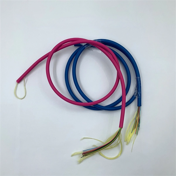
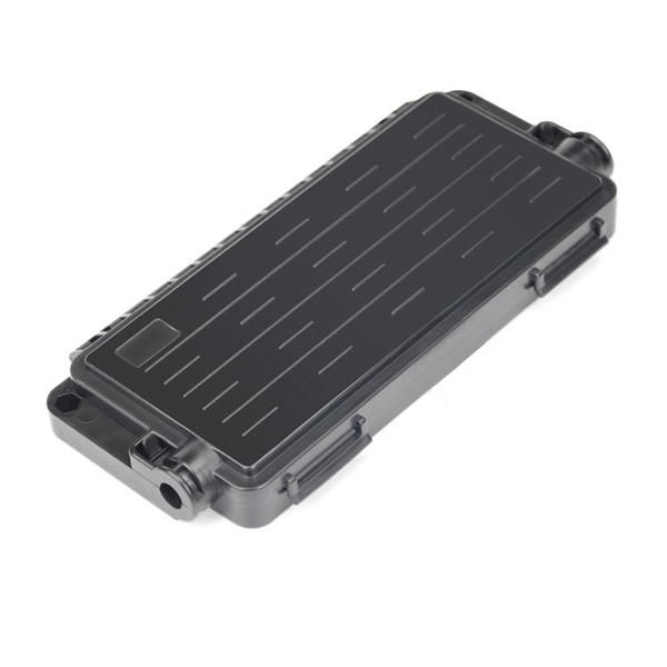
If you're new to fiber optics or want to enhance your technical skills, this guide will help you understand how to splice fiber pigtails safely and efficiently. --- 🔧 In This Video You'll Learn: ✅ What fiber pigtails are and why they're used ✅ How to strip, clean. The most efficient way to terminate a fiber run is by using a pigtail. A fiber pigtail is a short length of optical fiber that comes with a high-quality, factory-polished connector already installed on one end, leaving a length of exposed glass on the other. Instead of building a connector from. In this detailed video, we'll walk you through the fiber optic pigtail splicing process — from preparation to final testing. --- 🔧 In. Executive Summary: A fiber optic pigtail is one of the most commonly specified yet least understood components in structured cabling. Get the wrong connector type, the wrong polish, or skip proper fusion splicing technique—and you're looking at elevated signal loss, increased back reflection, and a. Break off the cable entry from the cover and from the back box. Tie the cable to the box and wrap the fibers around the center 2~3 times as shown.
[PDF]

In today's video, we'll be unboxing the 9-Port Power Supply Box and demonstrating how to connect the cables to provide power to CCTV cameras. A CCTV power supply box sends power to all your cameras from one place. It helps keep things neat and makes your system easier to manage. In this guide, you'll learn how to install it step by step, choose the right type, avoid common problems, and keep your system running safely. Power supply boxes for CCTV are typically used in multi-camera installations instead of using single power adapters for each camera. The process is almost exactly the same if you. Installers of surveillance systems may simply control the power to various CCTV cameras using a CCTV power supply box, also known as a power distribution box (usually at the location of the DVR). This enables a cleaner camera installation. Surge protection can be accomplished in two ways. The power supply box is specifically used to transfer power requirements for all cameras plugged in on the system, to work. Security cameras use RG59U coax siamese wire or CAT5e networking cable to transmit video. Whether you are installing a power box for a new or existing camera system, it is important to understand how to connect cameras to a CCTV Power Supply Box. DC current is polarized meaning it has two leads, a.
[PDF]

Instead of relying on assumptions, this guide offers a clear-eyed look at how to properly secure your fiber infrastructure, moving beyond the myths to implement practical, layered defenses that provide real-world protection for your organization's most sensitive data. For manufacturers and industry professionals involved in creating, deploying, or maintaining these critical systems, ensuring the robust and reliable securement of fiber optic cables is paramount. “Securing” fiber optic cable goes beyond just preventing it from moving; it encompasses protecting its. Fiber optic cables enable high-speed, long-distance data transfer, forming the backbone of modern communication. Yet, outdoors, they face temperature swings, moisture, UV exposure, rodents, and human interference. Protecting them is essential for long-term reliability. This guide covers how to. Fiber optic and ACSR (Aluminum Conductor Steel Reinforced) cables play a critical role in modern infrastructure, including power transmission and telecommunications. However, these cables face several challenges that can compromise their performance and longevity. If you are an optical engineer or a fiber optic network operator, you need to know how to protect your cables from these threats and ensure. An effective fiber optic network security plan acknowledges these potential weak spots and addresses them head-on. Before beginning any installation, safety.
[PDF]

The most efficient way to terminate a fiber run is by using a pigtail. A fiber pigtail is a short length of optical fiber that comes with a high-quality, factory-polished connector already installed on one end, leaving a length of exposed glass on the other. Instead of building a connector from. Installing fiber optic pigtails correctly is essential for ensuring low signal loss and long-term reliability. Remove the outer coating carefully to expose the fiber. Use alcohol wipes to remove dust and debris. Make a precise cut for optimal splicing. Align and fuse the pigtail fiber with the main. Executive Summary: A fiber optic pigtail is one of the most commonly specified yet least understood components in structured cabling. Get the wrong connector type, the wrong polish, or skip proper fusion splicing technique—and you're looking at elevated signal loss, increased back reflection, and a. A fiber optic pigtail is a short length of optical fiber with a connector pre-attached to one end. If you're new to fiber optics or want to enhance your technical skills, this guide will help you understand how to splice fiber pigtails safely and efficiently. --- 🔧 In. Fusion splicing involves precisely melting the ends of two optical fibers together, creating a seamless connection that minimizes signal loss. This method offers the lowest attenuation and reflectance, making it ideal for long-haul telecommunications. You can buy this fusion splicing kit here On.
[PDF]

How to Use Optical Power Meter TR-504 | Optical Power Meter Working| Testing OPM, VFL, RJ45 | TRICOM In this video, we walk you through how to use the TRICOM TR-504 Optical Power Meter and explain how it works. Learn how to test fiber optic cables, OPM, VFL . Optical power meters are a key element in the optimization and maintenance of such optical networks and of their components. In this article, learn: What is an optical power meter? An optical power meter (OPM) measures the power levels of light signals in devices that transmit data or power using. An optical power meter measures the strength of light traveling through a fiber optic cable, giving you a reading in dBm (decibels relative to one milliwatt). The basic process is straightforward: turn the meter on, set it to the correct wavelength, clean your connectors, plug in, and read the. OPM interface: insert the fiber to be tested, test the optical power. An optical power meter is a tool that measures the number of optical power in a cable is fiber-optic. It helps engineers verify the performance of optical fiber systems, ensuring that the signal strength meets requirements, and is an essential tool for communication network maintenance and troubleshooting.
[PDF]
Watch as we take you through the entire manufacturing process step by st. How to Make Electrical Pigtails: This is a basic tutorial on what electrical pigtails are and how to make them. Disclaimer: Always use multiple sources and do your homework before performing any electrical work. Also, make sure all work is done within national and local code. Combining is putting the layers of linerboard and medium together to form complete corrugated board. Medium is engineered to form easily into flutes as it is fed between two large gear-like rollers on the Wet End of the corrugator. Linerboard is engineered to remain flat as it adheres to the top. A corrugated box is a packaging carton made of a fluted (wavy) inner layer sandwiched between two flat sheets of paper. The thickness of the inner and outer sheets can be customized as per a brand's needs and the nature of the product. The three-layer structure creates a box that is both strong and. Pigtails act as bridges, allowing you to connect several wires to a single point without overloading connections. Professionals often prefer this method because it isolates issues, protecting downstream circuits from cascading failures. Why does this matter? Modern systems demand precision. A. The corrugated box manufacturing process involves several stages, beginning with paper rolls and ending with finished packaging boxes ready for shipment. These paper rolls are loaded onto the.
[PDF]

Learn how to properly install a pigtail connector in just a few easy steps. No description has been added to this video. Enjoy the videos and music you love, upload original content, and share it all with friends, family, and the world on YouTube. Pigtail connections are most frequently used to ground a switch or electrical outlet and for electrical devices that need to connect to multiple circuit wires. They also come in handy to lengthen circuit wires that are too short to reach a device. A pigtail is composed of three strands of wire. A pigtail connector is a short length of insulated electrical wire that is pre-attached to a device, terminal, or fixture, serving as a flexible bridge between the fixed wiring system and the component. Whether you are a DIY enthusiast or someone facing an electrical issue, understanding how to replace a pigtail connector can be invaluable. This article will walk you through the necessary steps and provide. This is where quality automotive connector replacement steps in. Often, rather than pay thousands of dollars for an entire harness, you can simply replace the damaged connector by a careful de-pin/re-pin or an accurate wire repair. Want more automotive electrical wire repair videos? Click Here Hear. The National Electrical Code (NEC) requires a pigtail to be at least six inches long. Although this standard applies to house wiring, we can use the same for vehicle wiring.
[PDF]

An optical module's actual transmit power measured by an optical power meter is lower than the nominal transmit power of the power module. The possible causes are: Bores of the optical module are contaminated. Stable optical power is the foundation of every high-capacity optical transport system. Even minor deviations—whether too high, too low, or unstable—can impact signal integrity, trigger service alarms, or interrupt traffic on DWDM, OTN, or long-haul optical line systems. This is the domain of Cell-to-Module (CTM) power loss, a series of. This paper reviews methods for reducing different optical and electrical loss mechanisms in PV modules and for increasing the optical gains in order to achieve higher CTM ratios. Various solutions for optimizing PV modules by means of simulations and experimental prototypes are recommended. Have you ever experienced an unexpected network outage due to the failure of an SFP/SFP+ optical transceiver? Network outages can bring your ability to communicate and work to a halt, and your IT team will likely be frantically looking for a solution. It is important to understand how to. This article provides an in-depth analysis of two key performance indicators of optical modules: transmitter power and receiver sensitivity. Transmitter power characterizes the average optical power output from the laser under rated conditions, while receiver sensitivity indicates the minimum.
[PDF]

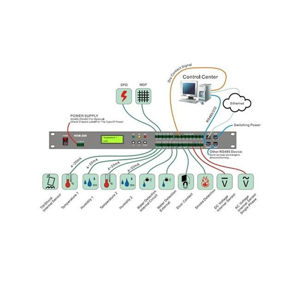
Voltage droop is the temporary reduction in the output voltage of a power source that occurs when the system suddenly draws a significant amount of electrical current. This drop is a fundamental consequence of electricity moving through materials that are not perfect conductors. The sudden increase. Voltage anomalies in telecom power systems disrupt network stability, often causing unexpected outages and costly downtime. Operators face significant challenges when faults go undetected, risking both equipment and service reliability. Power-related failures account for nearly one-third of telecom. Voltage stability in power systems can be impacted by various disturbances; including faults, load changes, equipment failures, and weather events. Instability can cause severe issues like loss of load, cascading outages, and the loss of synchronism in generators. Every conductor, regardless of material or size, possesses some amount of resistance that impedes current flow and converts electrical energy. Voltage dropping is a power quality condition where voltage at equipment terminals falls below expected operating levels during load conditions, causing instability, fluctuating performance, and observable changes in electrical system behavior. It is dynamic, load-driven, and often intermittent. Voltage drops and power losses in power lines are common and normal phenomena. They are associated with the flow of current through the different network components.
[PDF]
The enclosure is made of bent steel plates, featuring a compact structure, easy maintenance, and flexible circuit scheme combinations. Besides air circuit breakers and fuses for circuit protection, the distribution cabinet can also be equipped with contactors and thermal relays. Mauritius power strips and PDU power distribution units for surface mount, rack mount and general purpose applications. Multiple outlet power strips are manufactured in accordance to Mauritius standards with agency approvals. Designed for safety and durability, our range includes solutions for residential, commercial, and industrial electrical setups in Mauritius. Practibox S surface mounting cabinet with earth terminal blocks -. Mauritius is one of the world's most renowned island destinations, attracting millions of visitors each year with its tropical beaches, luxury resorts, and vibrant tourism industry. Behind the smooth operation of hotels, restaurants, and resort facilities lies a critical requirement: stable and. The transmission and distribution system forms the backbone of electricity supply in Mauritius, ensuring reliable power delivery from generation facilities to customers across the island. How the System Works Electricity is transmitted at higher voltages from generation sources to Bulk Supply. The XL type low-voltage power distribution cabinet uses domestically designed new components. The answer lies in upfront. Meta Description:.
[PDF]
We provide high-quality products including electrical plugs, cables, switches, solar systems, and power distribution components that meet international standards. Delivering advanced high & low voltage switchgear, distribution cabinets and energy storage solutions to power Iraq's industrial and infrastructure growth Certified, field-proven switchgear and distribution cabinets engineered to meet Iraq's demanding industrial environments Understanding the. In the realm of electrical equipment and supplies, iraq electrical cabinet play a crucial role in protecting sensitive electronics and instruments. These enclosures are designed to house and safeguard electronic components from environmental factors such as dust, moisture, and physical damage. ALMUSSAIB Unit 3 Major Turbine Generator & amp, Bop Rehabilitation. Amman Technology Company was established in Amman /Jordan in 2005. ALRASIKH and ALMERJAL are two Iraqi companies specialized in Power Generation, Power Distribution, Oil and Gas Industry. Your application has been sent. Al Ebtida is an Iraqi company specialized in supplying power distribution products & systems to the Iraqi market. We established long term partnerships with international manufacturers in order to supply your projects with high quality & reliable products.
[PDF]