
To use a power meter for fiber optic testing, always clean connectors first with lint-free wipes or click-to-clean tools. Select the correct wavelength and set your reference. You measure optical power in dBm or insertion loss in dB. Consistent procedures ensure accuracy. Verify light travels from. The most basic fiber optic measurement is optical power from the end of a fiber. This measurement is the basis for loss measurements as well as the power from a source or presented at a receiver. Typically both transmitters and receivers have receptacles for fiber optic connectors, so measuring the. An optical power meter measures the strength of light traveling through a fiber optic cable, giving you a reading in dBm (decibels relative to one milliwatt). This article will guide you through the methods, instruments, and key considerations for measuring fiber. Fiber optic cabling is the high-performance core of today's datacom networks. As network speeds and bandwidth demands increase, fiber performance requirements have become more stringent. Fiber testing is more important than ever. An OPM uses a photodiode to generate an electrical current proportional to optical power.
[PDF]

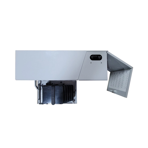
In this video, we'll show you how to connect an energy meter to a distribution board (DB) safely and efficiently. energy meter connection with distribution box How to Connect an Energy Meter to Your Distribution Box Easily Steps to Properly Connect Your Energy Meter to a Distribution Box. It plays a vital role in ensuring the safe and efficient distribution of electricity throughout the premises. What is the wire from the meter to the breaker box? Also. Always begin with disconnecting the main supply before accessing any enclosure containing distribution components. This prevents arc faults and ensures safety when modifying or inspecting current paths. This “meter to panel” wiring establishes the pathway for all incoming electrical power from the grid to the home. Its primary function is to safely and reliably. Distribution Board aslo know as “Panel Board”, “Switch & Fuse Board” or “Consumer Unit” is a box installed in the building containing on protective devices, such as circuit breaker, fuses, isolator, switches, RCDs and MCBs etc. The electric main supply (230V AC & 120V AC in US) is connected through. Changed Texas's reference diagram for the 3 wire network 120/208 Volt single phase self-contained Revised Figures 13, 14, 14b. Limited the meter location from pad mount transformer for PSO. Removed unistrut being listed as an alternative means for mounting the meter box. APCo and TX do not allow.
[PDF]

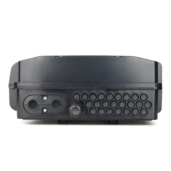
In today's video, we'll be unboxing the 9-Port Power Supply Box and demonstrating how to connect the cables to provide power to CCTV cameras. A CCTV power supply box sends power to all your cameras from one place. It helps keep things neat and makes your system easier to manage. In this guide, you'll learn how to install it step by step, choose the right type, avoid common problems, and keep your system running safely. Power supply boxes for CCTV are typically used in multi-camera installations instead of using single power adapters for each camera. The process is almost exactly the same if you. Installers of surveillance systems may simply control the power to various CCTV cameras using a CCTV power supply box, also known as a power distribution box (usually at the location of the DVR). This enables a cleaner camera installation. Surge protection can be accomplished in two ways. The power supply box is specifically used to transfer power requirements for all cameras plugged in on the system, to work. Security cameras use RG59U coax siamese wire or CAT5e networking cable to transmit video. Whether you are installing a power box for a new or existing camera system, it is important to understand how to connect cameras to a CCTV Power Supply Box. DC current is polarized meaning it has two leads, a.
[PDF]

A neat, well-organized subpanel bundles wires to conserve space and improve access. Ideally, wire groups are installed in layers and wires are bent at right angles to buses or breakers. Label short sheathing sections (slugs) to indicate which circuits wires serve. We cover everything from separating color-coded wires and securing them with ties to. Discover 7 DIY tips to organize your electrical panel for improved safety, easier troubleshooting, and efficient maintenance. Prevent hazards while making your home's electrical system more manageable. A disorganized electrical panel isn't just an eyesore—it's a safety hazard and troubleshooting. According to NEC (National Electric Code: Article 1 00-Definitions), a Main Panel (also known as Panelboard, load center, breaker box and distribution board etc. ) is a cabinet or cutout box which contains on controlling and protective devices (such as circuit breakers, fuses, switches etc. ) used to. Welcome to this live training session! ⚡ In today's tutorial, I'll be demonstrating how to arrange cables neatly inside a distribution bo. more See what others said about this video while it was live. If you're struggling with unsightly cords hanging around your cabinets, worry not! In this guide, we'll explore practical strategies to conceal those wires effectively. Before starting the process of.
[PDF]

Instead of relying on assumptions, this guide offers a clear-eyed look at how to properly secure your fiber infrastructure, moving beyond the myths to implement practical, layered defenses that provide real-world protection for your organization's most sensitive data. For manufacturers and industry professionals involved in creating, deploying, or maintaining these critical systems, ensuring the robust and reliable securement of fiber optic cables is paramount. “Securing” fiber optic cable goes beyond just preventing it from moving; it encompasses protecting its. Fiber optic cables enable high-speed, long-distance data transfer, forming the backbone of modern communication. Yet, outdoors, they face temperature swings, moisture, UV exposure, rodents, and human interference. Protecting them is essential for long-term reliability. This guide covers how to. Fiber optic and ACSR (Aluminum Conductor Steel Reinforced) cables play a critical role in modern infrastructure, including power transmission and telecommunications. However, these cables face several challenges that can compromise their performance and longevity. If you are an optical engineer or a fiber optic network operator, you need to know how to protect your cables from these threats and ensure. An effective fiber optic network security plan acknowledges these potential weak spots and addresses them head-on. Before beginning any installation, safety.
[PDF]

The primary and backup data centers, planned for the Absheron and Hajigabul regions, will incorporate advanced technologies to minimize carbon emissions. These facilities will feature energy efficiency, water conservation, waste recycling, and natural cooling systems to preserve. We currently have 3 data centers listed, from 1 markets in Azerbaijan (Az?rbaycan). Click on a market below, to explore its data center locations. Save the trouble of contacting the providers yourself, check out our Quote Service. The European Investment Bank will provide €43 million ($44. First reported by Azernews, the funding will be used to develop two data centers for AzInTelecom LLC which will be located Absheron and Hajigabul regions. AzInTelecom. Two innovative data centers utilizing green technologies and decarbonized materials will be constructed in Azerbaijan, operated by "AzInTelecom" LLC under the Ministry of Digital Development and Transport. Work is underway in Azerbaijan to launch two new data centers as part of ensuring the transition of all government institutions to the Government Cloud and in order to expand cloud services,.
[PDF]

In this blog, we'll walk through the standard procedures for installing racks and assembling MPO systems in modern data centers. Before any hardware is installed, detailed planning is essential. Rack placement must consider airflow, power distribution, cable routing, and physical. Proper installation of components in a data center server rack is crucial for optimal performance, efficient maintenance, and long-term reliability of your IT infrastructure. The term breaks down into two distinct phases: “racking” involves assembling and mounting servers, switches, storage devices, and networking equipment into. Best Practices for Data Center Rack and Stack Installation in 2025. Data centers are the backbone of modern technology, and ensuring their infrastructure is installed correctly can significantly impact performance and scalability. Data. However, before you get down to installation itself, it's necessary to prepare for it. A preparatory stage includes several important pre-installation steps that ensure smooth and durable functioning. These include: Choosing the right rack type. Server furniture differs a lot. Modern manufacturers. Four-Post Racks To mount two-post racks, the equipment has to be bolted to two vertical posts, in most cases at the front. They are simple, cheaper than other types, and occupy less space. They are a good choice for small IT rooms or closets with minimal depth requirements and lightweight devices.
[PDF]
Optical modules, also known as optical transceivers, are essential components that convert electrical signals to optical signals and vice versa. They form the backbone of long-distance, high-capacity data transport in modern telecom networks. A common question arises: “Are switches optical switching devices?” The answer is nuanced—optical transceivers combined with switches form a complete. Optical modules are essential components in modern communication networks, enabling high-speed data transmission over fiber optic cables. As the demand for faster and more reliable internet connections grows, understanding these devices becomes increasingly important. Deployed across fronthaul, midhaul, and backhaul. Optical transceivers are used for information storage, generation, and extraction between various devices within a data center. As AI models grow more complex and datasets balloon in size, traditional copper-based interconnects are. Modern data centers increasingly rely on interconnects for delivering critical communications connectivity among numerous servers, memory, and computation resources. Data center interconnects turned to optical communications almost a decade ago, and the recent acceleration in data center.
[PDF]

The core measurement procedure follows five steps: Turn on the meter and let it warm up. Most meters need a brief stabilization period before readings are reliable. Check your model's manual, but a minute or two is typical. Set the wavelength to match your light source. Fiber loss is the difference between the power when light is coupled from the transmitting end to the fiber and the power when the light reaches the receiving end. Generally speaking, when measuring the. An optical power meter measures the strength of light traveling through a fiber optic cable, giving you a reading in dBm (decibels relative to one milliwatt). The basic process is straightforward: turn the meter on, set it to the correct wavelength, clean your connectors, plug in, and read the. A power meter and light source are essential test tools that work in tandem to measure fiber optic cable loss and evaluate the quality of optical links. They provide the data necessary to quantify signal loss and pinpoint issues that could impact network performance. Here's how they work: A power. You measure optical power in dBm or insertion loss in dB. Verify light travels from transmitter to receiver. We'll give you the basic information you need and provide some printable references.
[PDF]
The European market for prefabricated and modular data centers is projected to grow to $4. 08 billion by 2034, driven by AI, 5G, and EU regulatory demands. Europe's digital transformation is literally being built on modules. Discover the top 10 companies driving the future of modular data centres with innovative, scalable and sustainable infrastructure solutions As computing demands surge, modular data centres are redefining how infrastructure is built, scaled and operated. Designed for rapid deployment, efficiency and. Vertiv's Infrastructure Solutions provide the flexibility, scalability, and efficiency that traditional infrastructures can't offer. Over the past decade, a notable shift has occurred in data center construction methods. In the past, traditional “brick and mortar” approaches involved piecing. Dublin, May 16, 2025 (GLOBE NEWSWIRE) -- The "Europe Prefabricated and Modular Data Centers Market: Focus on Data Center Types, Configuration, Form Factor, and Country Analysis and Forecast, 2024-2034" report has been added to ResearchAndMarkets. 42 billion in 2025 and USD 18. 6% during the forecast period. 0 USD Million by 2035, exhibiting a compound annual growth rate (CAGR) of 7. 3% during the forecast period 2025 - 2035 The Europe modular data-center market is experiencing robust growth driven by. The Europe modular data centre market was valued at USD 8. Market snapshot Quick.
[PDF]

In this video, we'll walk you through the process of resurrecting y. The test sets display a laser warning icon when the laser source is active to alert the user about a potentially dangerous situation. It is recommended to: Deactivate the laser before connecting or disconnecting optical cables or patchcords. more Is your optical power meter showing no signs of life? Don't worry; we've got you covered! In. Introduction The RP460 Optical Power Meter is an ultra low cost, and compact power meter used for verifying both absolute and relative power across any given fiber. This document will serve as an overview of the major features and functions of the device and will offer tips for trouble shooting. Fiber Optical Powermeter User Manual | FS Title Author Subject Keywords Created Date. The OPM1315 is a newly developed portable optical power meter. It is equipped with a 1. 0 mm large area detector so that stability and reliability can be enhanced effectively. This unit is designed to fit the hand comfortably, and can be used for installation, debugging, and maintenance of any fiber. ments to the instrument's performance and functionality. The figures given in this manual ion of this manual to ensure the accuracy of its contents. However, should you have any questions or fi gistered users with a variety of information and services. Please allow us to serve you best by.
[PDF]

Testing solar panels is easy with a multimeter! To test the current, simply connect the multimeter to the panel's output. Set it to read DC current. A multimeter is an indispensable tool for anyone working with solar panels, allowing for accurate measurements and diagnostics. It empowers users to assess the performance, identify faults, and ensure optimal energy production. Without proper testing and maintenance, solar panels can suffer from. In this article, you will learn the step-by-step process of testing your solar panels using a multimeter. We will cover the essential tools you need, the specific measurements to take, and how to interpret the results. By the end of this guide, you will be equipped with the knowledge to diagnose. With just a simple tool—a multimeter —you can quickly measure your panel's voltage and current. This helps you spot issues early and keep your system running efficiently. Connect the multimeter. 🔋 Learn how to test solar panels using a multimeter — step-by-step! I'll show you how to safely check voltage, amperage, and open-circuit power, so you can confirm if your panels are producing the watts you expect. Perfect for DIY solar builders, RV owners, o. We'll also introduce the Honeytek HK78G 2000V PV Multimeter, a professional tool designed for solar testing. Honeytek, a global.
[PDF]

Here's a comprehensive guide to the 15 best optical power meters for fiber techs in 2025, offering expert insights and reviews to help you find the perfect tool for your needs. Also, please take a look at the list of 26 optical power meter manufacturers and their company rankings. Novanta Photonics, 3. What Is an Optical Power Meter? What Is an Optical Power Meter? An optical. | | | | | |. Optical power meters measure the average optical power (energy per unit time) of continuous-wave (CW) or high-repetition-rate pulsed light sources. They are distinct from optical energy meters, which measure the energy of single light pulses, although some consoles support both sensor types. They. Optical power meters and detectors have been served by Newport for over 30 years. The offering ranges from a low cost, hand-held meter to the most advanced dual channel benchtop power meter available in the market. Our 1936-R/2936-R series boasts state-of-the-art analog boards with a whopping 250. HPC-50BVhandheld optical power meter has compactsize and high reliability. It can make accurate measurement on seven operating wavelengths (850/980/1300/1310/1490/1550 /1625nm). ST800K-UC SC/ST/FC Li battery with USB, -70~+10 dbm optical power meter. Optical Power Meters from ADC Corporation are listed on GoPhotonics. Use the filters to.
[PDF]

A good laser source for a singlemode link will have a power output of ~ +3 to +6 dBm - 2-4mw - coupled into the fiber. Tx power (transmission power) refers to the intensity of the optical signal output by the transmitting end of the optical module. However, in practical use, we adopt the average Tx power. These modules, including SFP, SFP+, and SFP28, are widely used in enterprise networks, data centers, and carrier-grade deployments. Optical loss is measured in “dB” which is a relative measurement, while absolute optical power is measured in “dBm,” which is dB relative to 1mw optical power Loss is a negative number (like –3. 2 dB) while power measurements can be either positive (greater than the reference) or negative (less than. SFP (Small Form-Factor Pluggable) modules are compact transceivers that allow for high-speed communication between network devices. They are essential in applications like telecommunications, data centers, and enterprise networks. Generally, the power levels are specified in terms of transmit (TX) power and. Transmit power is the power at which the transmitter of an optical transceiver module transmits optical signals in dBm. When the signal received is outside of the range, there is a.
[PDF]
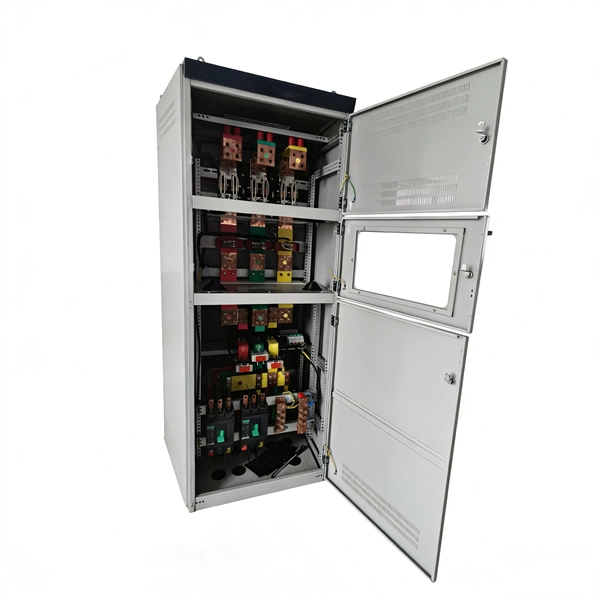
Busbars are essential components in electrical power systems, designed to distribute power efficiently within switchgear, panel boards, and distribution boards. Made from copper or aluminum, they serve as a central point where multiple circuits can connect, ensuring stable and. A bus bar (also spelled busbar) is a metallic strip or bar used in electrical power distribution to conduct electricity within a switchboard, distribution board, substation, or other electrical apparatus. Its primary role is to carry large current loads and connect multiple circuits together. In virtually every piece of electrical equipment—from switchgear and power distribution panels to EV battery packs and AI data centers—busbars play a vital, if often unseen, role. These components are the silent conductors of power, ensuring efficient energy distribution, reliability, and compact. Busbars (bus bars) are a type of electrical conductor that, compared to traditional cables, allow for the transmission of current in a safer and more flexible manner. They ensure efficient and effective energy distribution, successfully powering single- and three-phase devices and machines, and. Busbars offer a clean, efficient way to manage power distribution, simplifying complex wiring jobs and boosting reliability.
[PDF]