This guide covers the critical steps, from selecting the right electrical cable tray and performing accurate cable fill calculations to managing a safe cable pull through and ensuring all bonding and grounding requirements are met. Article Summary: A compliant cable tray installation requires a thorough understanding of NEC Article 392, proper structural support, and precise installation techniques. But before you lay the first tray or clamp down a single cable, you need a solid plan. This guide breaks down the process step by step. Here is a step-by-step guide on how to install a standard metal cable tray system (e., ladder or perforated type). Before starting, ensure you have. NEMA VE2 addresses cable tray installation and provides information on maintenance and system modification. NEMA VE2 was developed by the NEMA Cable Tray Section, of which MP Husky is a charter member. Ladder Cable Trays Solid side rail protection and system strength with smooth radius fittings and a wide selection of materials and finishes. Maximum strength for long span applications. Welcome to our step-by-step guide on installing cable trays! In this video, we'll explore the different types of cable trays available and provide detailed instructions for their installation. Whether you're an experienced electrician or a DIY enthusiast, this video is perfect for you.
[PDF]
In this step-by-step tutorial, we'll cover: ✅ Tools you need ✅ Safety precautions ✅ Mounting the box ✅ Wiring tips ✅ Final checks Perfect for beginners, DIYers, and electricians who want a clear installation guide. more Learn how to properly install an electrical. Learn how to install a distribution box safely and correctly. Covers wiring, placement, standards, and expert tips for a compliant setup. A distribution box is the heart of any electrical system. It takes the incoming power and safely distributes it to different circuits throughout your building. Before starting the installation, finding a proper place for putting the distribution box is crucial, because it largely decides the safety and convenience of maintenance. Let's see what factors need to be taken care of when choosing the installation place. Whether it is residential buildings, commercial facilities or industrial sites, the. Dear Mr. Electrician: How do I install an electrical box in a narrow space? NOTE: Text links below go to applicable products on Amazon. As an Amazon Associate, I earn from qualifying purchases. Using my links helps to keep this website FREE. Warm reminder: Do not disassemble or modify without experience and professionals. Select location Before.
[PDF]
This guide walks you through a safe, code-aware way to add a weather-ready receptacle near planting beds or a patio. If local rules differ, follow your jurisdiction's code and pull a permit when needed. Pick a spot that keeps the box out of splash zones and mower paths. Installing an outdoor GFCI receptacle in a garden takes planning, code-rated parts, and safe wiring in conduit or UF cable. Great for adding outlets, lighting, or appliances outside. more Need outdoor power? In this video, I'll show you how to install a weatherproof outdoor. Installing an outdoor electrical outlet can significantly enhance the functionality of your outdoor space, making it easier to power tools, lights, and appliances without fuss. This article details the process of installing them, which helps you comprehend distribution boxes. This comprehensive guide will equip you with the expert knowledge to safely install your outdoor electrical box, from understanding crucial wiring tips and essential GFCI protection to implementing industry best practices. Let's illuminate your outdoor projects, the right way. However, proper installation is essential for safety and local code compliance. The good news is that you don't need.
[PDF]
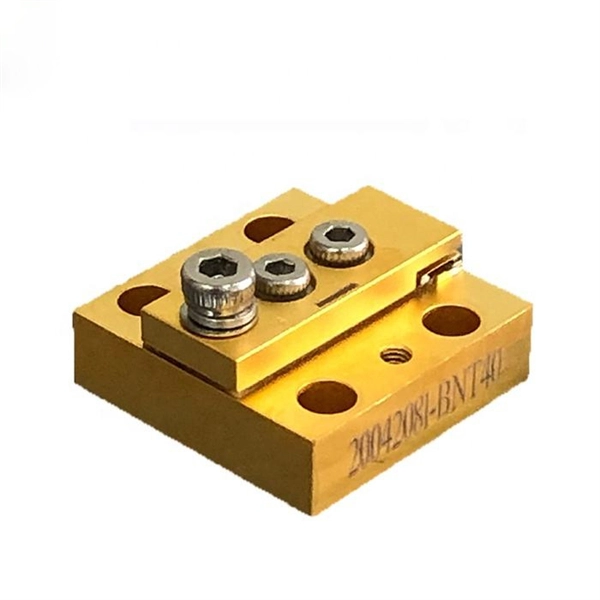
Cube beamsplitters eliminate beam displacement without being fragile. They are easy to mount and mechanically durable, but the presence of an interface can limit power handling if epoxy is used for bonding. I am looking for a beam splitter with the following properties: Polarising, so that one path is for p polarised light, and the other path for s polarised. Similar performance across a range of angle of incidence. I have been looking and either I can't find what I am looking for, or I just get. Many people don't know what a beam splitter is and wonder if they need it or not to use a smartphone adaptor on the microscope or slit-lamp. The beam splitter is found on most trinocular microscopes and some slit lamps. The beam splitter splits the light that travels up to the camera in two. A beam splitter (or beamsplitter, power splitter) is an optical device which can split an incident light beam (e. a laser beam) into two (or sometimes more) beams, which may or may not have the same optical power (radiant flux). This division allows for the simultaneous analysis or utilization of the light's properties along two separate paths. One beam is typically reflected while the other is transmitted. The ratio of reflected to transmitted light can vary based on the design of the beam splitter. It is a crucial part of many optical experimental and measurement systems, such as interferometers, also finding widespread application in fibre optic telecommunications.
[PDF]
Proper installation of an electric meter box is essential for safety, code compliance, and smooth coordination with your utility provider. A small mistake in mounting location or wiring can lead to failed inspections, service delays, or fire risks. A meter box is an electrical enclosure designed to house the electricity meter and related service connections. It acts as the formal interface between the utility power supply and the consumer's internal electrical system. That small enclosure becomes a shared responsibility. Electricians install it. Utilities connect it. If the location is wrong, the issue spreads quickly:. Panelboards shall be installed in accordance with the listing of the panelboard. The National Electrical Code (NEC) provides comprehensive safety standards for electrical installations, including requirements for electrical panels (main service panels and subpanels or breaker box). NEC Article 408. Limited the meter location from pad mount transformer for PSO. Removed unistrut being listed as an alternative means for mounting the meter box. APCo and TX do not allow unistrut for installations. 7/2020 Revised Figure 15. Added wording for consistency with Section 8 of document. The utility company uses this reading for billing. Its primary purpose is to safely contain the meter, protect internal.
[PDF]
For a straightforward installation of a single standard box in an accessible location, homeowners often see $120-$260. Projects involving new or upgraded circuits, larger panels, or difficult access commonly run $800-$1,600, with high-end setups surpassing $3,000 in some. Homeowners typically pay a broad range for electrical box installation, driven by box type, wiring complexity, and local labor rates. This guide covers cost, price ranges, and practical budgeting for standard electrical box installation projects. The cost includes materials, labor, and possible inspections or upgrades to meet code requirements. The price depends on electrical code upgrades, permit. Electrical panel replacement costs range from $518 to $2,188, and your total reaches up to $4,500. The amperage your home needs and the type of panel you choose will determine your final project cost for the replacement. You should budget for permits, drywall repairs, and wiring upgrades so your. Non-discounted retail pricing for popular: 100 amp 20-space 20-circuit indoor, breaker plug-on neutral load center. Circuit breakers not included. Basic labor to install electrical service panel with favorable site conditions. Connect wiring for up to 12 circuits. Install breakers. The average cost to replace a breaker box is $1,475 with most homeowners spending between $1,287 and $1,707. Total costs depend on the type of home, the number of circuits, and the amperage.
[PDF]
This guide provides instruction on how to install and configure your MS130R series switch. For more switch installation guides, refer to the switch installation guides section on. This guide provides step-by-step instructions for installing two common types of industrial switches: rack-mount, and DIN-rail switches. Choose the Installation Location: Select an appropriate spot on the DIN rail for mounting. This chapter describes how to start your switch and how to interpret the power-on self-test (POST) that ensures proper operation. No prior experience needed—just follow along and you'll have your switch installed and running in minutes. more In this video you'll see a complete, step-by-step guide to mounting. This typeface indicates command syntax, or represents information as it is displayed on the screen. When you see the word enter in this guide, you must type something, and then press the Return or Enter key. Do not press the Return or Enter key when an instruction simply says type. Here, we explore the four most common installation methods for industrial switches: Desktop installation is the most straightforward approach— placing the switch like a small box directly on a table, control panel surface, or equipment rack without extra fixtures. Simple setup: No tools required.
[PDF]
There are porcelain, high-voltage bushings on the cover connected to the primary line. Disconnecting switches or plug connectors shall be installed to permit the disconnection of all ungrounded conductors of each temporary circuit. All lamps for general illumination shall be protected from accidental contact or breakage. Metal-case sockets shall be grounded. Temporary lights shall. There are three main types of electrical switchgear: low-voltage (LV), medium-voltage (MV), and high-voltage (HV). Low-voltage switchgear is a common type of electrical switchgear used in various industries to regulate systems up to 1kV. It controls power flow and isolates electrical equipment, and it acts as a central hub. Recent studies indicate that up to 70% of electrical distribution system failures originate from. High-voltage switchgear is are essential electrical product used across power generation, transmission, distribution, conversion, and consumption. They manage switching, control, and protection functions for voltages from 3. High voltage switches are specialized devices designed to operate under elevated voltages, typically above. High Voltage Switchgear (HV/HT), often referred to as HV (High Voltage) or HT (High Tension) switchgear, is a vital part of modern power systems. You'll find it in power plants, substations.
[PDF]
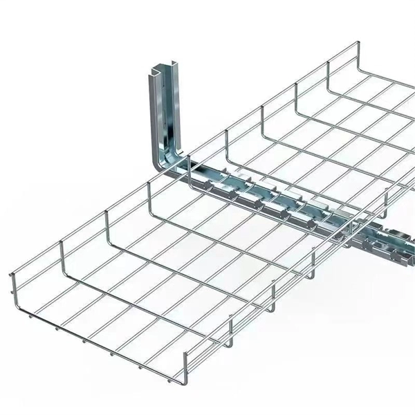
Students trading aid on how best to put an internal 90 degrees bend in steel cable tray. Videos are training aids for City and Guilds 5357 (C and. The bends, tees, crosses, risers and reducers of wire mesh cable tray can be easily and quickly made live at the project by using a bolt cutter. Since the jaws of the bolt cutter drags a layer of zinc across the cut end and forms a protective layer. When a wire cable tray is cut, the fact that a. You can buy a manufactured 90 degree bend or make one on a cable tray bending machine but in this video I show you how to make one using a metal bar. Electrical UK Wiring == 🕐. How many wires can fit in one tray? One should never fill up a tray. The general safety regulations state th/at a person is advised to fill 40-50 percent of the available space. The reason behind this is that the electricity-carrying wires become hot. This involves a few essential steps to ensure a successful bending process. Each example of bends and tee's clearly illustrate proper tray cutting combined with recommended usage of Cablofil accessories. Engineers and contractors in North America and around the world have found. The first step is to mark out the tray (A). Construction of a flat 90° bend (A) The amount of tray lip to be removed is equal to 2, 3/4 the width of the tray, half of this measurement will be removed on either side of the centre line. To remove the lip we can use a small hand grinder (B) or a file.
[PDF]

Your trusted fiber internet provider and tech repair shop in Lebanon. High-speed connectivity, quality devices, and expert support since 2009. Over 15 years of trusted service in Lebanon Lightning-fast fiber optic internet connection Serving Nabatieh & surrounding. Fiber Works & Communications (FWC) S. has been participating in the Lebanese enterprise market for several years now, attaining an honorable reputation of FIBER OPTIC Expertise when it comes to high speed & wide area networks. We trust on providing excellent European & American products, as. We found 19 listings in Lebanon Horsh Tabet – Sin el Fil, Group Center, 3rd Floor, Beirut, Lebanon Turnkey solutions for networks, cabling, and security systems., Jnah (BHV), Beirut, Lebanon Supplying diverse electronic components and tools for all users. IDM fiber delivers to both corporate and residential customers a reliable Internet connection with unprecedented speeds reaching 1 Gbps. The new solution, also known as Fiber to The Home or FTTH will answer all your current and future high bandwidth needs, both for downloads or uploads, allowing. Fiber to the x (FTTX) is a generic term for any broadband network architecture using optical fiber to provide all or part of the local loop used for last mile telecommunications. Our vision is to assist in protection of people and properties by providing quality innovative products & solutions.
[PDF]

The FLS-140 is the easiest way to identify optical fibers from end to end and locate polished connector endfaces. Its red laser shines through most yellow-jacketed optical fibers to help you pinpoint breaks, bends, faulty connectors, splices and other causes of signal loss. A Visible Fault Identifier (VFI), also referred to as a Visual Fault Locator (VFL), is an essential tool for fiber installation and maintenance technicians. AFL's compact VFI4 injects high-powered red-laser light to provide exceptional brightness and range for locating defects in single-mode and. The B5 Rechargeable Red Light Pen is a professional 650nm visual fault locator designed for fiber optic network maintenance, installation, and troubleshooting. Its advanced rotary automatic lift laser head ensures smooth operation, while the integrated LED lighting improves visibility in low-light. Whether installing or troubleshooting, the Visual Fault Locator (VFL) is an essential tool that quickly and easily locates problem areas in fiber cables. By pinpointing the exact location of fiber damage, technicians can diagnose, troubleshoot, and fix the problem efficiently. The VFL is also used. The state, throughput, and identification of an optical fiber can be easily checked with fiber testers by coupling highly visible laser light into the optical fiber. A high intensity visible red laser beam is precision-coupled.
[PDF]
This article outlines five specific steps for repair: 1) Identify the break; 2) Cut out the damaged section; 3) Strip the cable; 4) Trim the fiber ends; 5) Test the repair. DIY fiber optic cable repair kits are increasingly popular for those who prefer home repairs. Before diving into repairs, it's essential to grasp the basics of fiber optic cables. These cables consist of a core (glass or plastic) that carries light signals, surrounded by cladding to reflect light inward, a buffer for protection, and an outer jacket for durability. Single-mode fibers (SMF). With the right tools and techniques, you can efficiently repair damaged fiber cables and restore reliable performance. The first step requires that you find the damage. To do this, you can use an OTDR, Optical Time Domain, Reflectometer. This is a testing device that looks at optical signals in the cable which can identify irregularities in the structure. This involves a set of specialized equipment such as a fusion splicer, fiber cleaver, and fiber stripper, among others. When it comes to ensuring nice network experiences for users, the condition of a fiber. A cut or damaged fiber optic cable can disrupt your network, but it is repairable with the right tools and techniques.
[PDF]
Welcome to our step-by-step guide on installing cable trays! In this video, we'll explore the different types of cable trays available and provide detailed instructions for their installation. Whether you're an experienced electrician or a DIY enthusiast, this. Whether you're building a commercial setup or upgrading an industrial plant, proper cable tray installation ensures neat wiring, safe access, and easy maintenance. But before you lay the first tray or clamp down a single cable, you need a solid plan. This guide breaks down the process step by step. Installing a cable tray system requires careful planning to ensure it can support the weight of the cables and adheres to electrical safety codes. Here is a step-by-step guide on how to install a standard metal cable tray system (e., ladder or perforated type). more. The purpose of this article is to define the sequence and methodology for the installation of electrical cable trays, cable trunking, cable raceways and boxes, junction and pull boxes. The method gives details of how the work will be carried out and what health and safety issues and controls that. Cable tray systems are designed for easy installation and to accommodate power, communications, and signal cabling across a variety of applications. When installed and engineered properly, cable.
[PDF]
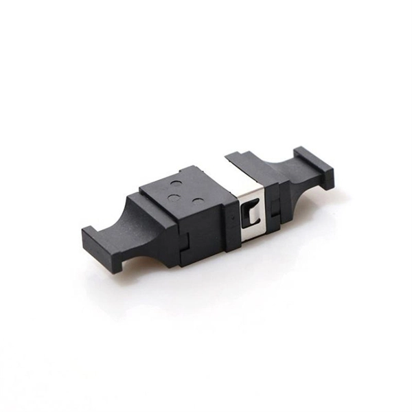
Please view our full RLH price list and contact us at info@fiberopticlink. com if you have any questions or special project needs. A Fiber Optic Patch Panel, also known as an Optical Distribution Frame (ODF) or fiber termination enclosure, is a centralized hardware unit designed to manage, protect, and organize fiber optic cable connections. In an era where data speeds and network reliability are non-negotiable, the patch. fiber optic patch panel, odf, optical distribution frame, fiber distribution panel, rack mount fiber patch panel, wall mount odf, fiber termination box, 1u fiber patch panel, 24 port fiber patch panel, 48 port fiber patch panel, outdoor fiber patch panel, fiber optic odf, sliding patch panel The. Q1: What is the difference between an ODF and a patch panel? An ODF is the entire frame or cabinet managing fiber connections, while a patch panel is a modular unit inside the ODF for cross-connecting fibers. Q2: How many fibers can an ODF handle? It depends on the ODF type; rack-mount units can. ODF is used in the terminal access link of FTTH system. It is a device that splices, distributes, and splits optical fibers and provides protection and management of optical fibers. Belden offers several Fiber Patching Systems. Full patching platforms include FX ECX for LAN environments, FX UHD for high-density fiber channels and the DCX System used primarily in data centers where high amounts of fiber connections and density are the key requirements, as in optical.
[PDF]

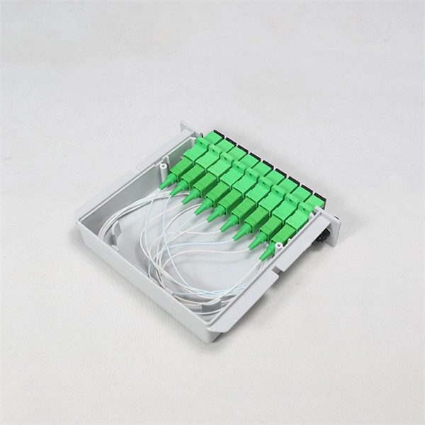
The NanoSpeed™ Series 1×4 solid-state fiber-optic splitter splits the optical power among four outputs with any power splitting ratio. The input is polarization-maintaining (PM) fiber and the outputs are four single mode or PM fibers. Thorlabs offers a wide range of optical beamsplitters. Our plate beamsplitters have a coated front surface that determines the beam splitting ratio while the back surface is wedged and AR coated in order to minimize ghosting and interference effects. Pellicle beamsplitters provide excellent. Beamsplitters are optical components used to split input light into two separate parts. Beamsplitters are also ideal for fluorescence applications, optical interferometry, or life science or semiconductor instrumentation. Light. PLC (Planar Lightwave Circuit) Splitters are designed for single-mode applications and offer an even split ratio from one input fiber to multiple output fibers. Circular beamsplitters, plate beamsplitters and cube beamsplitters can be purchased for polarizing or non polarizing beamsplitting. OZ Optics Online. This is achieved using patent pending non-mechanical.
[PDF]